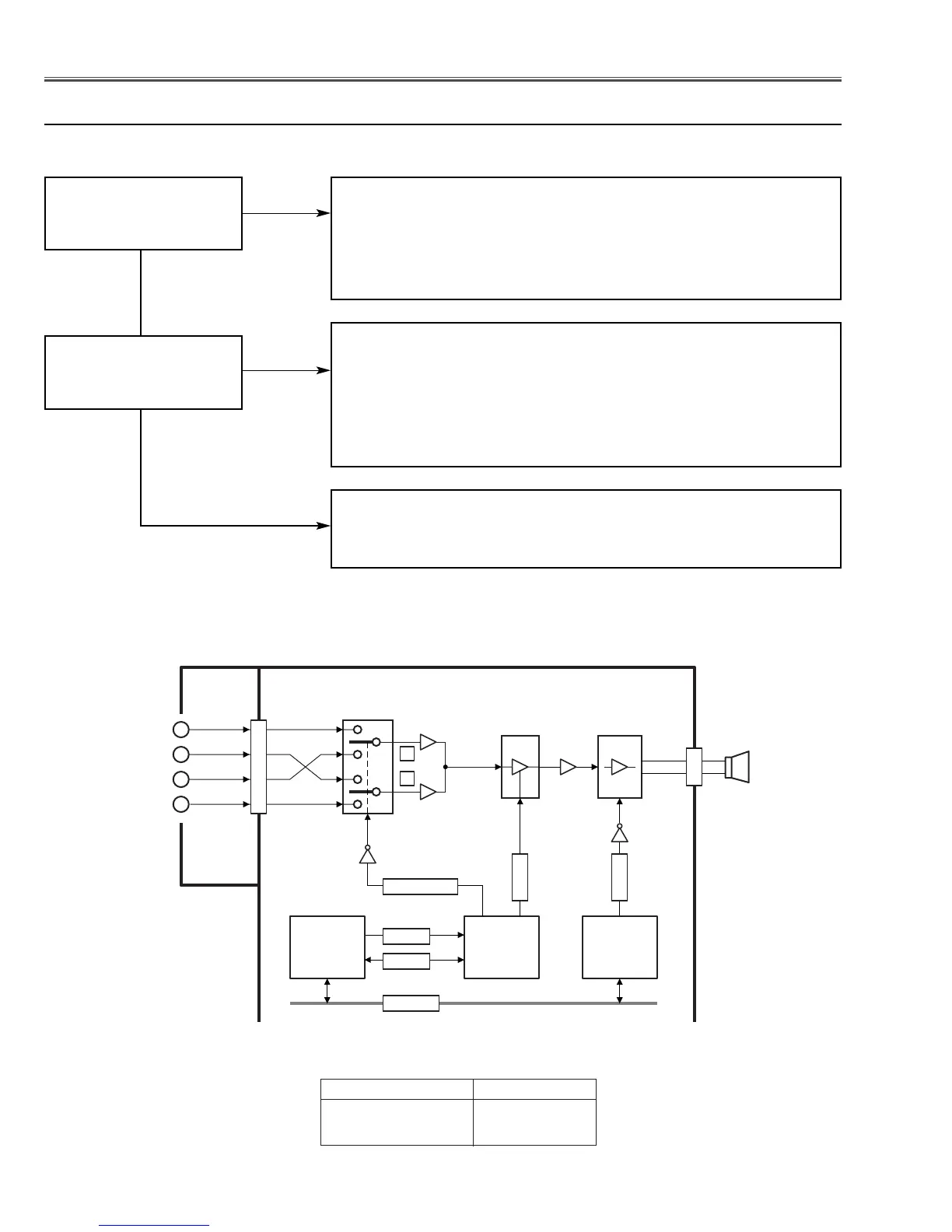
EasyManua.ls Logo

Sanyo PLC-SW30 - Control and Reset Options; Remote Control Codes and Key Lock; System Resets

Sanyo PLC-SW30
81 pages
To Next Page IconTo Next Page
To Previous Page IconTo Previous Page
Loading...
-38-
Troubleshooting
Q5002
Q5006
Q5003
Q5001
Q5004
12
10
2
1
14
1
5
3
3
8
121312
5
13
Mute: H
Mute: L
K8F
K50B
K10E
P_SCLK2
P_SCDA2
AUD_PC/AV_SW
VOLUME
MAIN BOARD
AV
BOARD
IC5003
AMP.
<LM4865M>
IC5002
VOLUME
<BA7655A>
L
R
L
R
L
R
PC
AUDIO-IN
AV
AUDIO-IN
SP901
IC1801
OUTPUT
EXPANDER
<74LCX574>
IC3551
D/A
CONVERTER
<M62393>
IC301
SYSTEM
CONTROL
<PW168A>
PC AV
AUD_PC/AV_SW at IC3551 H L
AUD_PC/AV_SW at IC5001 L H
AUDIO-SW Switching Logic
MUTE
IC5001
AUDIO-SW
<4052>
+ 2 +
4
8
9
10
11
1
3
+
-
DATA B U S
Audio signal processing circuit
No Sound
Check AUD_PC/AV switching circuit.
Check IC5001, audio-sw IC, and peripheral circuit.
AUD_PC/AV_SW (PC:H) signal is applied on pin 10 of IC5001
through Q5003, sent from pin 12 of IC3551.
Is the audio signal
observed at pins 3 and
13 of IC5001?
Check Audio amp.and control circuit.
Check IC5003, audio-amp IC, and peripheral circuit.
MUTE signal (Mute:L) is applied on pin 4 of IC5003, sent from
pin 12 of IC1801.
VOLUME signal is applied on pin 2 of IC5002., sent from pin 13 of
IC3551.
Check 5V_AUD power supply line.
Is the audio signal
observed at pins 5 and
8 of IC5003?
Check audio output circuit.
Check speaker, connection of the terminal “K8F”.
Ye s
No
Ye s
No
Check following steps.

Other manuals for Sanyo PLC-SW30

Related product manuals