1. Receive the 16-step gray scale computer signal with
COMPUTER IN [RGB] mode.
2. Enter the service mode.
3. Connect an oscilloscope to test point “TPR1” (+) and
chassis ground (-).
4. Select item no. “7” and change data value to adjust
waveform “a” to be minimum amplitude.
5. Connect an oscilloscope to test point “TPG1” (+) and
chassis ground (-).
6. Select item no. “8” and change data value to adjust
waveform “a” to be minimum amplitude.
7. Connect an oscilloscope to test point “TPB1” (+) and
chassis ground (-).
8. Select item no. “9” and change data value to adjust
waveform “a” to be minimum amplitude.
(a)
White Level
-23-
● Circuit Adjustments
CAUTION: The each circuit has been made by the fine adjustment at factory. Do not attempt to adjust the follow-
ing adjustments except requiring the readjustments in servicing otherwise it may cause loss of per-
formance and product safety.
Electrical Adjustments
[Adjustment Condition]
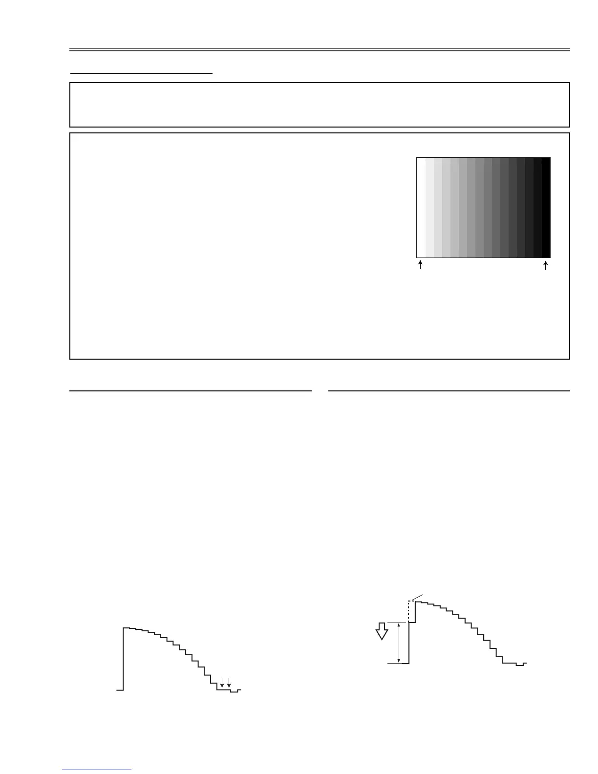
● Input signal
Video signal .......................... 1.0Vp-p/75Ω terminated, 16 steps gray
scale, white 100% and white 50% pat-
tern (Composite video signal)
Computer signal .................... 0.7Vp-p/75Ω terminated, 16 steps gray
scale pattern (SVGA)
Component Video signal........ 0.7Vp-p/75Ω terminated, 16 steps gray
scale, white 100% and black 0% pat-
tern (480i format and 480p format)
● Picture control mode ................ “STANDARD” mode unless otherwise
noted.
Note:
* Please refer to “Service Adjustment Menu Operation” for entering to the service mode and adjusting the service
data.
White 100%
Black 100%
x PC Gain adjustment
16 steps gray scale pattern
1. Receive the 16-step gray scale computer signal with
COMPUTER IN [RGB] mode.
2. Enter the service mode.
3. Connect an oscilloscope to test point “TPR1” (+) and
chassis ground (-).
4. Select item no. “275” and change data value to adjust
the pedestal level and black level to be the same
level.
5. Connect an oscilloscope to test point “TPG1” (+) and
chassis ground (-).
6. Select item no. “276” and change data value to adjust
the pedestal level and black level to be the same
level.
7. Connect an oscilloscope to test point “TPB1” (+) and
chassis ground (-).
8. Select item no. “277” and change data value to adjust
the pedestal level and black level to be the same
level.
Black Lebel
Pedestal Lebel
 Loading...