-24-
1. Receive the 16-step gray scale component signal
(480i format) with COMPUTER IN [COMPONENT]
mode.
2. Enter the service mode.
3. Connect an oscilloscope to test point “TPR1”(+) and
chassis ground (-).
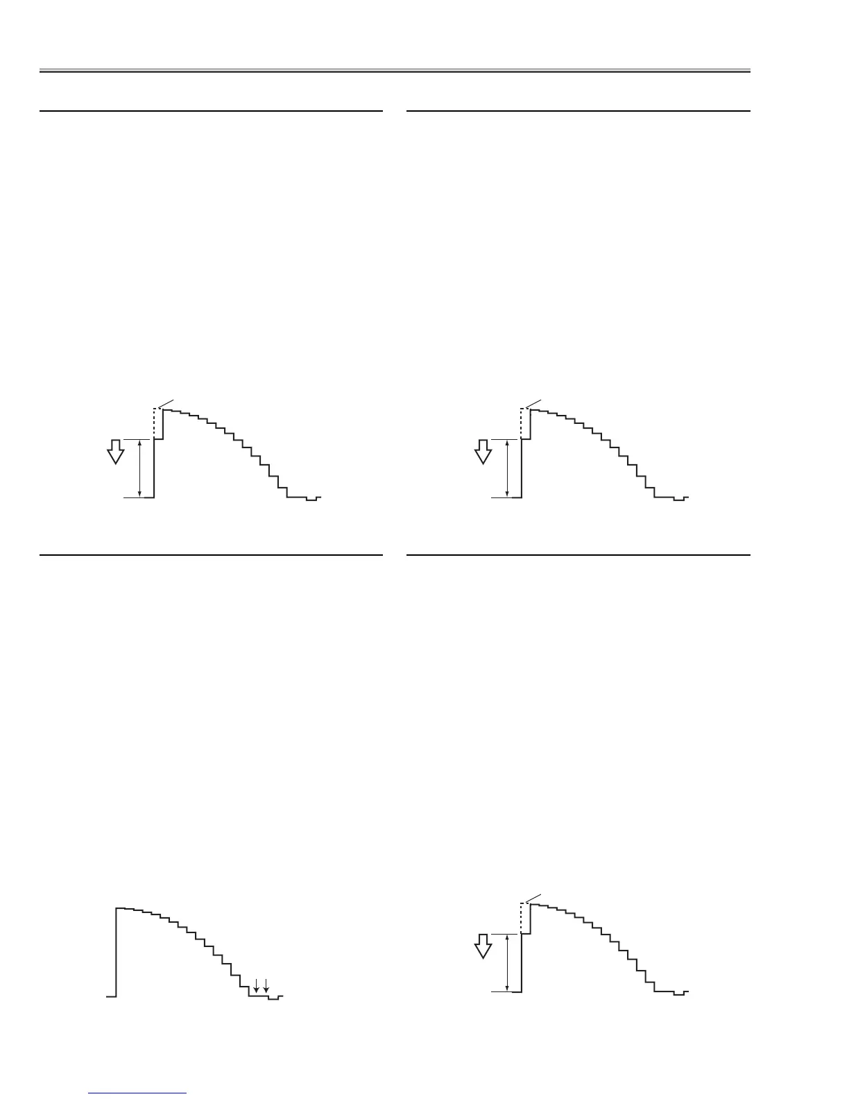
4. Select item no. “7” and change data value to adjust
waveform “a” to be minimum amplitude.
5. Connect an oscilloscope to test point “TPG1” (+) and
chassis ground (-).
6. Select item no. “8” and change data value to adjust
waveform “a” to be minimum amplitude.
7. Connect an oscilloscope to test point “TPB1”(+) and
chassis ground (-).
8. Select item no. “9” and change data value to adjust
waveform “a” to be minimum amplitude.
(a)
White Level
1. Receive the 16-step gray scale component signal
(480p format) with COMPUTER IN [COMPONENT]
mode.
2. Enter the service mode.
3. Connect an oscilloscope to test point “TPR1”(+) and
chassis ground (-).
4. Select item no. “7” and change data value to adjust
waveform “a” to be minimum amplitude.
5. Connect an oscilloscope to test point “TPG1” (+) and
chassis ground (-).
6. Select item no. “8” and change data value to adjust
waveform “a” to be minimum amplitude.
7. Connect an oscilloscope to test point “TPB1”(+) and
chassis ground (-).
8. Select item no. “9” and change data value to adjust
waveform “a” to be minimum amplitude.
(a)
White Level
1. Receive the 16-step gray scale composite video sig-
nal with Video [Video] mode.
2. Enter the service mode.
3. Connect an oscilloscope to test point “TPR1” (+) and
chassis ground (-).
4. Select item no. “7” and change data value to adjust
waveform “a” to be minimum amplitude.
5. Connect an oscilloscope to test point “TPG1” (+) and
chassis ground (-).
6. Select item no. “8” and change data value to adjust
waveform “a” to be minimum amplitude.
7. Connect an oscilloscope to test point “TPB1” (+) and
chassis ground (-).
8. Select item no. “9” and change data value to adjust
waveform “a” to be minimum amplitude.
(a)
White Level
c Video Gain adjustment
Electrical Adjustments
b 480p Gain adjustment
n 480i Gain adjustment
1. Receive the 16-step gray scale component signal
(480p format) with COMPUTER IN [COMPONENT]
mode.
2. Enter the service mode.
3. Connect an oscilloscope to test point “TPR1” (+) and
chassis ground (-).
4. Select item no. “275” and change data value to adjust
the pedestal level and black level to be the same
level.
5. Connect an oscilloscope to test point “TPG1” (+) and
chassis ground (-).
6. Select item no. “276” and change data value to adjust
the pedestal level and black level to be the same
level.
7. Connect an oscilloscope to test point “TPB1” (+) and
chassis ground (-).
8. Select item no. “277” and change data value to adjust
the pedestal level and black level to be the same
level.
Black Lebel
Pedestal Lebel
v 480p Pedestal adjustment
 Loading...