EasyManua.ls Logo

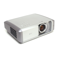
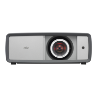
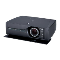
Sanyo PLV-Z3 Service Manual

Sanyo PLV-Z3
94 pages
To Next Page IconTo Next Page
Page #1 background imageLoading...
Page #1 background image
PRODUCT CODE
1 122 268 00 PLV-Z3 (S)
(M4SA)
1 122 269 00 PLV-Z3 (S) (P4SA)
1 122 269 02 PLV-Z3 (S) (P4SC)
1 122 268 20 PLV-Z3 (K) (M4SAA)
1 122 269 20 PLV-Z3 (K) (P4SAA)
1 122 269 22 PLV-Z3 (K) (P4SCA)
REFERENCE NO. SM5110679-00
Multimedia Projector
SERVICE MANUAL
FILE NO.
Model No. PLV-Z3
(U.S.A., Canada, Europe
Asia, Africa, U.K. )
Chassis No. M4S-Z300
M4S-Z3S00
NOTE: Match the Chassis No. on the unit’s
back cover with the Chassis No. in
the Service Manual.
If the Original Version Service
Manual Chassis No. does not
match the unit’s, additional Service
Literature is required. You must refer
to “Notices” to the Original Service
Manual prior to servicing the unit.
Original Version
Other manuals for Sanyo PLV-Z3

Questions and Answers:

Sanyo PLV-Z3 Specifications

General IconGeneral
BrandSanyo
ModelPLV-Z3
CategoryProjector
LanguageEnglish

Summary

Safety Instructions

SAFETY PRECAUTIONS

General safety guidelines and warnings for servicing the projector.

SERVICE PERSONNEL WARNING

Specific warnings for service personnel regarding lamp handling and electrical hazards.

Specifications

Technical Specifications

Detailed technical specifications for the multimedia projector, including dimensions, weight, and performance.

Circuit Protections

Warning temperature and power failure protection

How temperature and power failure protection mechanisms operate and indicate issues.

Lamp Replacement

Lamp Replacement

Steps and indicators for replacing the projector's lamp when its life ends.

Cleaning

Cleaning the Air Filter

Instructions for cleaning the projector's air filters to maintain cooling efficiency.

Mechanical Disassemblies

3. MAIN BOARD AND THERMAL BARRIER PLATE REMOVAL

Steps to remove the main board and thermal barrier plate.

8. OPTICAL UNIT AND FAN REMOVAL

Procedure to remove the optical unit and cooling fans.

Optical Parts Disassemblies

7. LOCATIONS IN OPTICAL UNIT

Diagram showing the correct placement of optical parts within the unit.

LCD Panel/Prism Ass'y Replacement

IMPORTANT NOTICE on LCD Panel/Prism Ass'y Replacement

Crucial notes regarding LCD panel replacement and necessary adjustments.

Adjustments After Parts Replacement

Optical Adjustment

Electrical Adjustment

Service Adjustment Menu Operation

How to enter and navigate the projector's service adjustment menu.

Service Adjustment Data Table

Location of Test Points

Chassis Block Diagram

Power Supply Lines

Troubleshooting

No Power

Troubleshooting steps for when the projector does not power on.

Indicators

Description of POWER and WARNING LED indicators and their meanings.

No Picture

Troubleshooting steps for situations where there is no picture output.

No picture with all of input sources

Steps for diagnosing no picture across all input sources.

No picture with COMPONENT1/2 (YCbCr 480i,575i) input sources

Troubleshooting specific to Component input sources.

No picture with HDMI (RGB digital) input source

Troubleshooting for no picture with HDMI input.

No picture with Computer (RGB analog) input source

Troubleshooting for no picture with RGB analog computer input.

No picture with Computer (RGB SCART) input source

Troubleshooting for no picture with RGB SCART input.

No picture with S-VIDEO input source

Troubleshooting for no picture with S-Video input.

No picture with video input source

Troubleshooting for no picture with composite video input.

Control Port Functions

IC Block Diagrams

Electrical Parts List

Mechanical Parts List

Related product manuals