Savant Low Voltage Keypad Deployment Guide 13 of 22
Copyright © 2019 Savant Systems, LLC
009-1731-00 | 190401
Making Connections
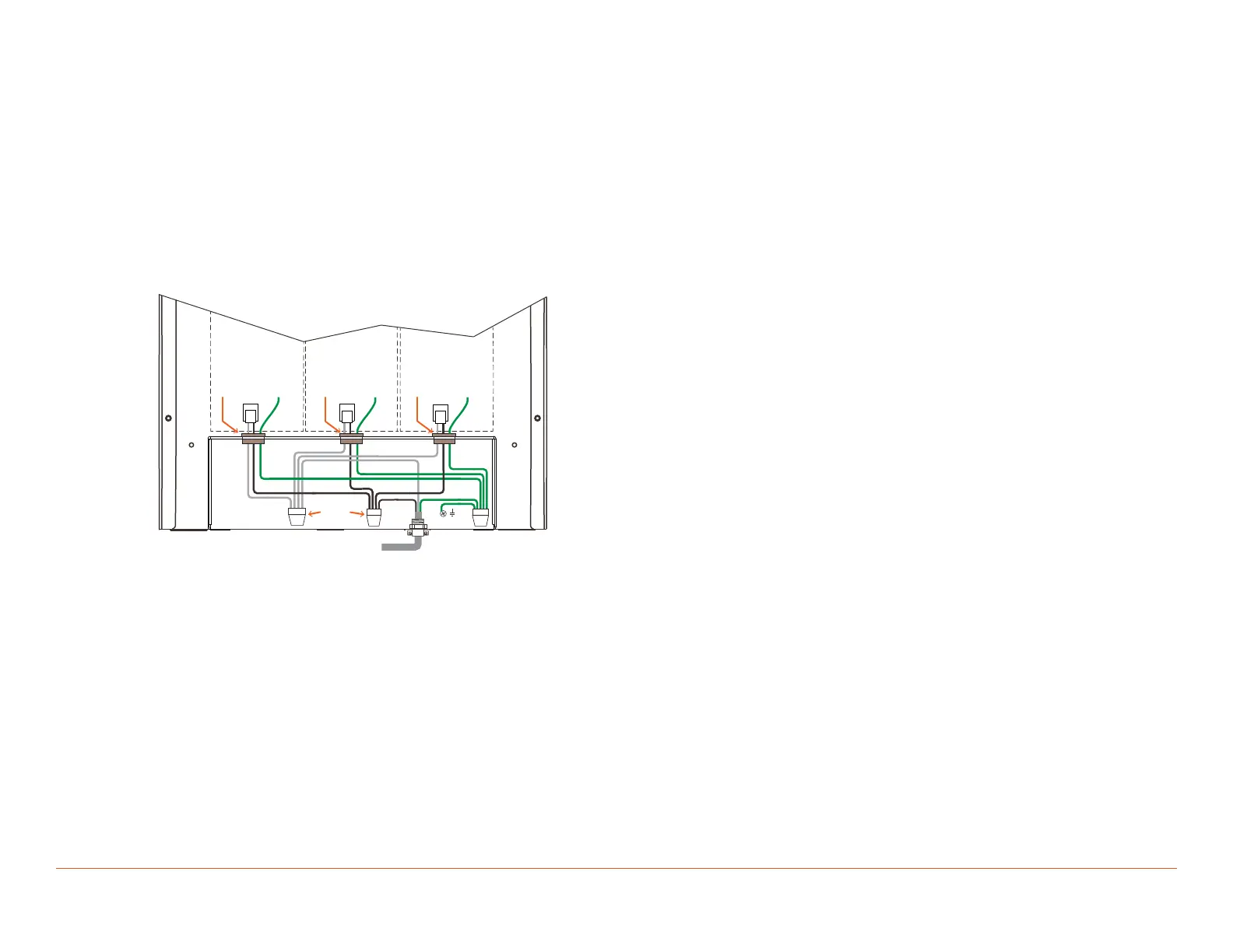
With all keypad modules installed, connect the white (neutral), black (hot), and green (ground) wires from each module to a 120/240V AC circuit. Use
the diagram for reference.
1. Verify the 120/240V AC feed from circuit breaker is o.
2. Strip approximately 10 inches of the outer jacketing from the electrical cable and insert wires through the electrical clamp installed in step 6 of the
Prepping Enclosure section. Tighten clamp.
3. Using the 6-position WAGO connector mounted to the green ground wire screwed to the enclosure, connect all ground wires together.
4. Using one of the WAGO 6-position push connectors included with the enclosure, connect all the neutral wires together.
5. Using one of the WAGO 6-position push connectors supplied with the enclosure, connect all the hot wires together.
6. Insert all wires into the AC compartment, and reinstall AC compartment cover.
7. Apply power by switching the breaker at the circuit breaker box to the On position.
Module
Slot 1
Module
Slot 2
Module
Slot 3
BUSHING
GND
ON PS
GND
ON PS
GND
ON PS
WAG O
CONNECTORS
BUSHING BUSHING
FROM 15 AMP BREAKER
GND

 Loading...