Settings P746/EN ST/G31
MiCOM P746 (ST) 4-
7
ST
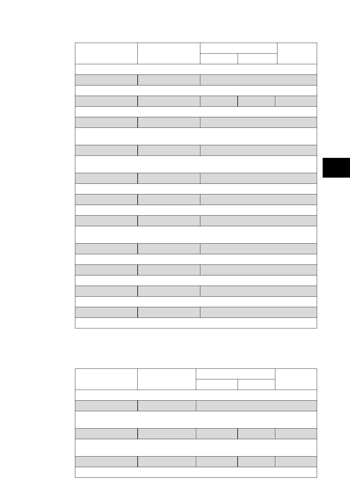
Setting Range
Menu Text Default Setting
Min. Max.
Step Size
OP Mode = Three Box Mode
Protected phase Phase A Phase A / Phase B / Phase C
Sets the connected phase to be protected (only available for three box mode).
Feed Numbers 6 0 18 1
Sets the number of feeders connected to the relay (up to 18)
Z1 terminals 0000000000000000 0 / 1
Sets the configuration of the terminals fixed to zone 1 from terminal 18 (1
st
digit) to
terminal 1 (last digit). The terminal is activated when its corresponding digit is set to 1.
Z2 terminals 0000000000000000 0 / 1
Sets the configuration of the terminals fixed to zone 2 from terminal 18 (1
st
digit) to
terminal 1 (last digit). The terminal is activated when its corresponding digit is set to 1.
Xfer Terminals 0000000000000000 0 / 1
Sets the configuration of the terminals that can be switched between the two zones.
ChZONE terminal 0000000000000000 0 / 1
Sets the configuration of the terminals that are needed for Check Zone
Bus Coupling by Breaker Breaker / none / Isolator
Sets the configuration of the bus coupling. It indicates whether bus is coupled by breaker,
isolator or none.
Z1 Bus CT No CT No CT / CT1 to CT18
Sets the busbar current transformer belonging to zone 1.
Z1 Bus CT Pol Standard Inverted / standard
Sets the direction of the busbar current transformer in zone 1.
Z2 Bus CT No CT No CT / CT1 to CT18
Sets the busbar current transformer belonging to zone 2.
Z2 Bus CT Pol Standard Inverted / standard
Sets the direction of the busbar current transformer in zone 2.
1.2.2 Differential protection configuration
The differential element has independent settings for phase and earth (sensitive) faults,
which are used for all zones and the check zone independently.
Setting Range
Menu Text Default Setting
Min. Max.
Step Size
DIFF PROTECTION
Busbar Diff Enabled Disabled / Enabled
To enable (activate) or disable (turn off) the busbar differential protection. If the function is
activated, the following options are accessible.
ID>2 Current 2.400 kA 50.0 A 30 kA 10.0 A
Setting that determines the minimum differential operating current for all the discriminating
zone biased differential elements.
Phase Slope k2 60.00 % 20.00 % 90.00 % 1 %
Slope angle setting for all the zones biased differential element.