P746/EN ST/G31 Settings
(ST) 4-
6
MiCOM P746
1.2 Protection settings
The protection settings include all the following items that become active once enabled in the
configuration column of the relay menu database:
− Protection element settings.
− Programmable scheme logic (PSL).
There are four groups of protection settings, with each group containing the same setting
cells. One group of protection settings is selected as the active group, and is used by the
protection elements. The settings for group 1 are shown. The settings are discussed in the
same order in which they are displayed in the menu.
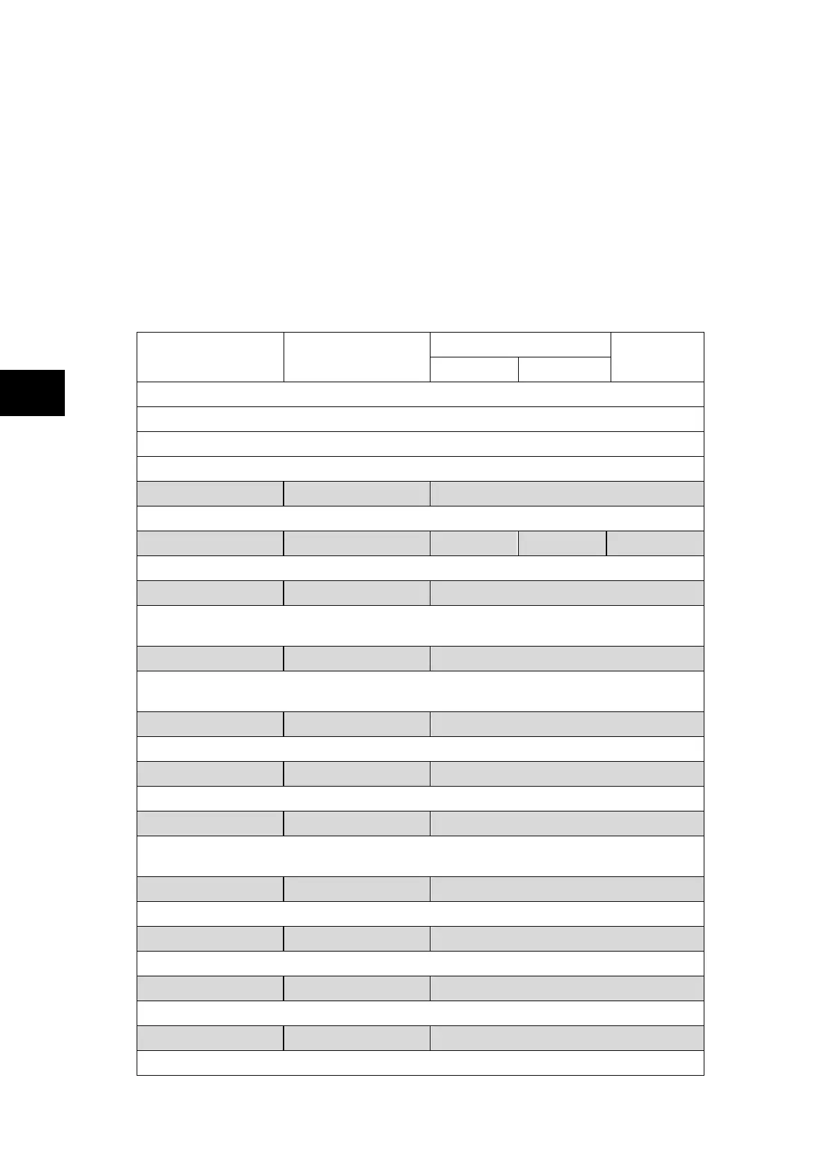
1.2.1 System Configuration
Setting Range
Menu Text Default Setting
Min. Max.
Step Size
SYSTEM CONFIG
OP Mode: One Box Mode / Three Box Mode
Displays one box mode or three box mode relay configuration (front panel only).
OP Mode = One Box Mode
Phase Sequence Standard ABC Standard ABC / Reverse ACB
Sets the phase sequence (standard or reverse, only available for one box mode)
Feeder Numbers 6 0 6 1
Sets the number of feeders connected to the relay (up to 6)
Z1 terminals 000000 0 or 1
Sets the configuration of the terminals fixed to zone 1 from terminal 6 (1
st
digit) to terminal
1 (last digit). The terminal is activated when its corresponding digit is set to 1.
Z2 terminals 000000 0 or 1
Sets the configuration of the terminals fixed to zone 2 from terminal 6 (1
st
digit) to terminal
1 (last digit). The terminal is activated when its corresponding digit is set to 1.
Xfer Terminals 011111 0 or 1
Sets the configuration of the terminals that can be switched between the two zones.
ChZONE terminal 011111 0 or 1
Sets the configuration of the terminals that are needed for Check Zone
Bus Coupling by Breaker Breaker / none / Isolator
Sets the configuration of the bus coupling. It indicates whether bus is coupled by breaker,
isolator or not (none).
Z1 Bus CT CT6 No CT / CT1 to CT6
Sets the busbar current transformer belonging to zone 1.
Z1 Bus CT Pol Inverted Inverted / standard
Sets the direction of the busbar current transformer in zone 1.
Z2 Bus CT CT6 No CT / CT1 to CT6
Sets the busbar current transformer belonging to zone 2.
Z2 Bus CT Pol Standard Inverted / standard
Sets the direction of the busbar current transformer in zone 2.
ST
 Loading...