THE PRESENT MANUAL BELONGS TO - Schenker Italia - ALL RIGHTS RESERVED
27
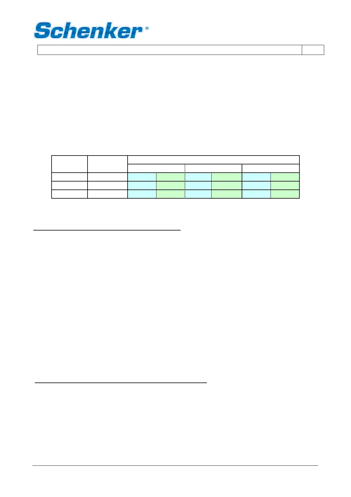
4.5.2 Electric connections: wires (SMART 100 12/24V DC)
The electric connectors are positioned inside the small electric box connected to the computer box. The power
supply, coming from the service batteries, needs to be connected to the terminals – and + . The connection
to the boat panel needs to be performed downstream the voltmeter and the ammeter of the boat panelboard.
The connecting terminal must be suitable to support the plant electric load (approx. 500 Watt). A 64 Ampere
automatic circuit breaker for 12V DC systems must be installed on the power supply , while a 32 Ampere for
24VDC systems.
The general wires connection scheme (between the external devices and the main electric box) is the following:
Electric cables and switches selection table
The connection general diagram is the following:
Clamp Position connect to cable section
- Pump box negative battery see table
+ Pump box positive battery see table
- Pump box Computer box see table
+ Pump box Computer box see table
P1 Pump box Computer box 2,5 mm2
PS Computer box Signal pressure switch 2,5 mm2
PS Computer box Signal pressure switch 2,5 mm2
EV Computer box electrovalve (on the AC filter) 2,5 mm2
EV Computer box electrovalve (on the AC filter) 2,5 mm2
Connection between the computer box and remote panel.
Connect the remote panel to the computer box using pre wired cable supplied (standard length 10 mts.)
 Loading...