www.scheppach.com / service@scheppach.com / +(49)-08223-4002-99 / +(49)-08223-4002-58
32
|
GB
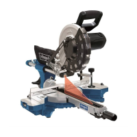
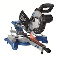
• Open the set screw (16b) for the moveable stop rail
(16a) and push the moveable stop rail (16a) out-
wards.
• The moveable stop rails (16a) must be locked so
that the distance between the stop rails (16a) and
the saw blade (6) is at least 8 mm.
• Before making a cut, check that the stop rails (16a)
and the saw blade (6) cannot collide.
• Re-tighten the set screw (16b).
• Move the machine head (4) to its upper position.
• -
dle (11).
•
the desired angle (refer also to point 10.5 in this re-
gard).
•
(14).
• Undo the set screw (22).
• Use the handle (1) to tilt the machine head (4) to the
left until it coincides with the required angle value (in
this connection see also section 10.6).
• Re-tighten the set screw (22).
• Cut as described under section 9.4.
10. Maintenance
m Warning! Prior to any adjustment, maintenance
or service work disconnect the mains power plug!
10.1 General maintenance measures
using a cloth. In order to extend the service life of the
motor.
When cleaning the plastic do not use corrosive prod-
ucts.
10.2 Cleaning the moving saw blade guard safety
device (5)
using the machine.
Remove old sawdust and splinters using a brush or
similar tool.
10.3 Replacing the table insert
Danger!
With a damaged table insert (10) there is a risk of
small parts getting stuck between table insert and saw
blade, blocking the saw blade. Immediately replace
damaged table inserts!
1. Remove screws at table insert. If required, turn
reach the screws.
2. Remove table insert.
3. Install new table insert.
4. Tighten the screws at table insert.
• The moveable stop rails (16a) must be locked so
that the distance between the stop rails (16a) and
the saw blade (6) is at least 8 mm.
• Before making the cut, check that the stop rails
(16a) and the saw blade (6) cannot collide.
• Secure the set screw (16b) again.
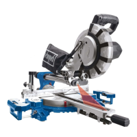
• Loosen the handle (11) if it is tightened. Pull the in-
dexed position lever (35) upwards with the pointer
-
gle using the handle (11).
•
table (15).
•
(14).
• Cut as described under section 9.4.
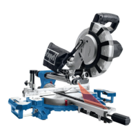
9.6 Mitre cut 0°- 45° and turntable 0°
(g. 1/2/11)
The crosscut, drag and mitre saw can be used to
make mitre cuts of 0° - 45° in relation to the work face.
Attention!
For bevel cuts (inclined saw head), the moveable stop
Left
side).
• Open the set screw (16b) for the moveable stop rail
(16a) and push the moveable stop rail (16a) out-
wards.
• The moveable stop rails (16a) must be locked so
that the distance between the stop rails (16a) and
the saw blade (6) is at least 8 mm.
• -
ner position. (Right side).
• Before making a cut, check that the stop rail (16a)
and the saw blade (6) cannot collide.
• Secure the set screw (16b) again.
• Move the machine head (4) to the top position.
•
• Loosen the set screw (22). Use the handle (1) to an-
gle the machine head (4) to the left, until the pointer
(19) indicates the desired angle measurement on
the scale (18).
• Re-tighten the set screw (22).
• Cut as described in section 10.4.
9.7 Mitre cut 0°- 45° and turntable 0°- 45°
(g. 1/2/4/12)
The crosscut, drag and mitre saw can be used to
make mitre cuts to the left of 0°- 45° in relation to the
work face and, at the same time, 0° - 45° to the left or
0° - 45° to the right in relation to the stop rail (double
mitre cut).
Attention!
For bevel cuts (inclined saw head), the moveable stop
Left
side).
 Loading...