www.scheppach.com
36
|
GB
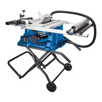
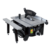
8.4 Mounting / dismounting the saw blade guard
(gs. 11 - 12)
1. Mount the saw blade guard (4) together with the
bolt (25) on top of the riving knife (6), so that the
2.
3. Plug the suction hose (5) onto the suction adapt-
er (26) and the connecting piece of the saw blade
guard (4). Connect a suitable splint collector onto
the suction adapter (26).
4.
Caution!
The saw blade guard (4) must be lowered onto
the workpiece before starting the sawing op-
eration.
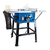
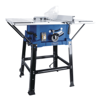
8.5 Replacing the bench insert (g. 8)
1. In case of wear or damage, the bench insert (2)
must be replaced; otherwise, there is an increased
2. Unfasten the bolt (23) using a Phillips screwdriver.
3. Take out the worn bench insert (2).
4. The installation of the new bench insert is done in
reverse order.
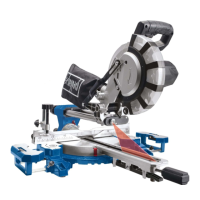
8.6 Installing / replacing the saw blade (g. 13)
1. Caution! Pull out the main plug and wear safe-
ty gloves.
2. Dismount the saw blade guard (4) (see 8.4)
3. Remove the bench insert (2) (see 8.5)
4.
(22a) on the nut while holding up another saw
22).
5. Caution! Turn the nut in the direction of rotation of
the saw blade.
6.
7.
brush before mounting the new saw blade.
8. Insert the new saw blade in reverse order and
tighten.
Caution! Note the direction of run, the cutting
slope of the teeth must be in the direction of
run, i.e. facing forward.
9.
blade guard (4) (see 8.4 and 8.5)
10.
4. Screw the support struts (21a, 21b) to the table
extensions (8) with the hex bolts (19) and cross
member (21c).
5.
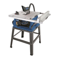
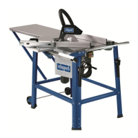
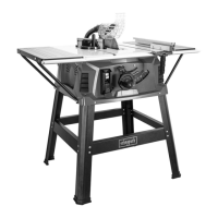
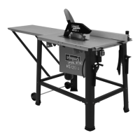
8.2 Mounting rack (gs. 6 - 7.1)
1. Screw the four support legs (16) together with the
support struts (22) onto the saw with the hex bolts
2. Now place the rubber feet (16a) onto the support
3. Now, screw the long centre brace (17) and the
short centre brace (18) onto the legs (16) using
the hexagon head bolts (19) and the hexagon
head nuts (20). Make sure that the same braces
face each other. The long centre braces (17 -
marked „B“) must be mounted parallel to the
operator‘s side of the saw. (Fig. 7).
4.
the hex nuts (20) at the drill holes of the rear sup-
Attention!
Both support frames must be fastened to the
back of the machine!
5. Then, tighten all the nuts and bolts of the under-
frame.
8.3 Setting / mounting the riving knife (gs. 8 - 10)
m The setting Caution! Pull out the main plug!
The setting of the riving knife (6) must be
checked prior to commissioning. of the riving
knife (6) must be checked prior to commis-
sioning.
1. Set the saw blade (3) to the max. cutting depth,
bring it to the 0° position and lock it.
2. Unfasten the bolt (23) from the bench insert (2) us-
ing a Phillips screwdriver, and remove bench insert
3. The distance between the saw blade (3) and the
4. Loosen the mounting bolt (24) in order to pull out
the splitting wedge (6) until the right distance is
5. Tighten the mounting screw (24) again and mount
the bench insert (2).