25
ROZPAKOWANIE MASZYNY
Proszę sprawdzić zawartość pod kątem ewentualnych
uszkodzeń.
W przypadku stwierdzenia uszkodzenia należy natych-
miast zawiadomić spedytora. Proszę sprawdzić kom-
pletność dostawy.
Brakujące części należy natychmiast zgłosić dystrybu-
torowi.
Dodatkowe części, które będą przymocowane do ma-
szyny, muszą być zlokalizowane i przyporządkowane
przed montażem.
Uwaga! Zakres dostawy urządzenia nie obejmuje
oleju silnikowego!
1 Ubijak wibracyjny
2 Opakowanie dodatkowe
3 Instrukcja obsługi
4 Uchwyt prowadzący
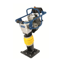
ELEMENTY OBSŁUGOWE IL. 1
1 Silnik
2 Zbiornik paliwowy
3 Korek wlewu paliwa
4 Zawór paliwowy (Zbiornik paliwowy)
5 Filtr powietrza
6 Wlew oleju
7 Korek spustu oleju
8 Dźwignia zasysacza
9 Włącznik zapłonu
10 Rozrusznik linkowy
11 Dźwignia regulacji gazu
12 Tłumik
13 Skrzynia biegów
14 Ubijak – dolna część
15 Stopa
16 Korek spustu oleju – stopa
17 Rama ochronna
18 Ochrona transportowa
19 Uchwyt do transportu
20 Płyty łącznikowe (2x)
21 Zawór paliwowy (Silnik)
Montaż
Z przyczyn wynikających z pakowania i transportu ma-
szyny, nie jest ona całkowicie zmontowana
Montaż płyt łącznikowych Il. 2
1 Zamontować 2 płyty łącznikowe (20) przy użyciu 4
śrub sześciokątnych M10x20 (A) po obu stronach
przekładni (13).
2 Dokręcić mocno śruby.
Montaż ram ochronnych Il. 2.1
1 Zamontować ramy ochronne (17) przy pomocy śrub
walcowych z łbem sześciokątnym M 10 x 20 (A) z
obu stron do płyty łącznikowe (20).
2 Dobrze dokręcić śruby.
UNPACKING THE MACHINE
Check the contents for possible transport damages.
In the case of damage, this must be reported to the car-
rier immediately. Check the content for completeness.
Report missing pieces to the dealer immediately.
Additional parts that are to be secured to the machine
must be located and assigned before the installation.
Caution! In the package, the device contains no
motor oil!
1 Vibration Rammer
2 Accessory kit bag
3 Operating instructions
4 Driving mechanism
CONTROLS FIG. 1
1 Motor
2 Petrol tank
3 Fuel cap
4 Fuel cock (Petrol tank)
5 Air lter
6 Oil ller neck
7 Oil drain screw
8 Choke lever
9 Ignition switch
10 Choke
11 Gas regulation lever
12 Mufer
13 Drive
14 Rammer- Base
15 Tamping foot
16 Oil drain screw for tamping foot
17 Safety frame
18 Transport protection
19 Transport handle
20 Adapter plates (2x)
21 Fuel cock (Motor)
Assembly
For packing-technical reasons, your machine is not
completely assembled
Mounting the adapter plates (Fig. 2)
1 Mount the 2 adapter plates (20) on both sides of
the transmission (13) using 4 hexagon screws M
10x20 (A).
2 Tighten the screws well.
Mount protective frame Fig. 2.1
1 Mount the protective frame (17) with 4 hex screws
M 10 x 20 (A) on both sides to adapter plates (20).
2 Tighten the screws well.