Installation and commissioning DATAEAGLE 4XXX Compact 3-3
Chapter 3 – Structure
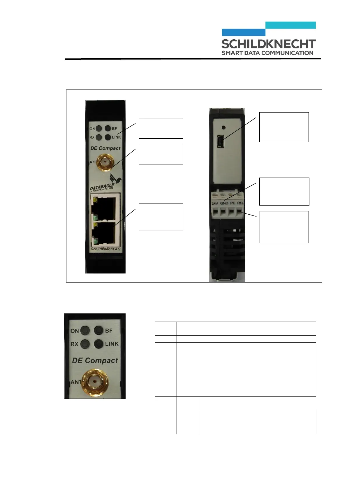
The illustration shows all connections of the radio module.
The table shows the significance of the LEDs at the
radio module:
Status display at Dataeagle Master
On: no reception of Ethernet telegrams
Flashing (Profinet):
Error (one of the connected PN partici-
pants is not exchanging data)
Off (Profinet): everything ok (all con-
nected PN participants are exchanging
data)
DE47XX:
Bluetooth connection established
DE43XX:
On or flashing when connected
USB
connection
(configuration)
Ethernet
connection
(Switch)
Relay output
(radio control)