Assembly
02.02|PWG-S 40 - 80|en
13
Assembly
Mechanical connection
WARNING
Risk of injury when the machine/system moves unexpectedly!
Switch off power supply.
The values relate to the entire bolting surface.
Requirements for levelness of the bolting surface (Dimensions in mm)
Diameter Permissible unevenness
< 100 < 0.02
> 100 < 0.05
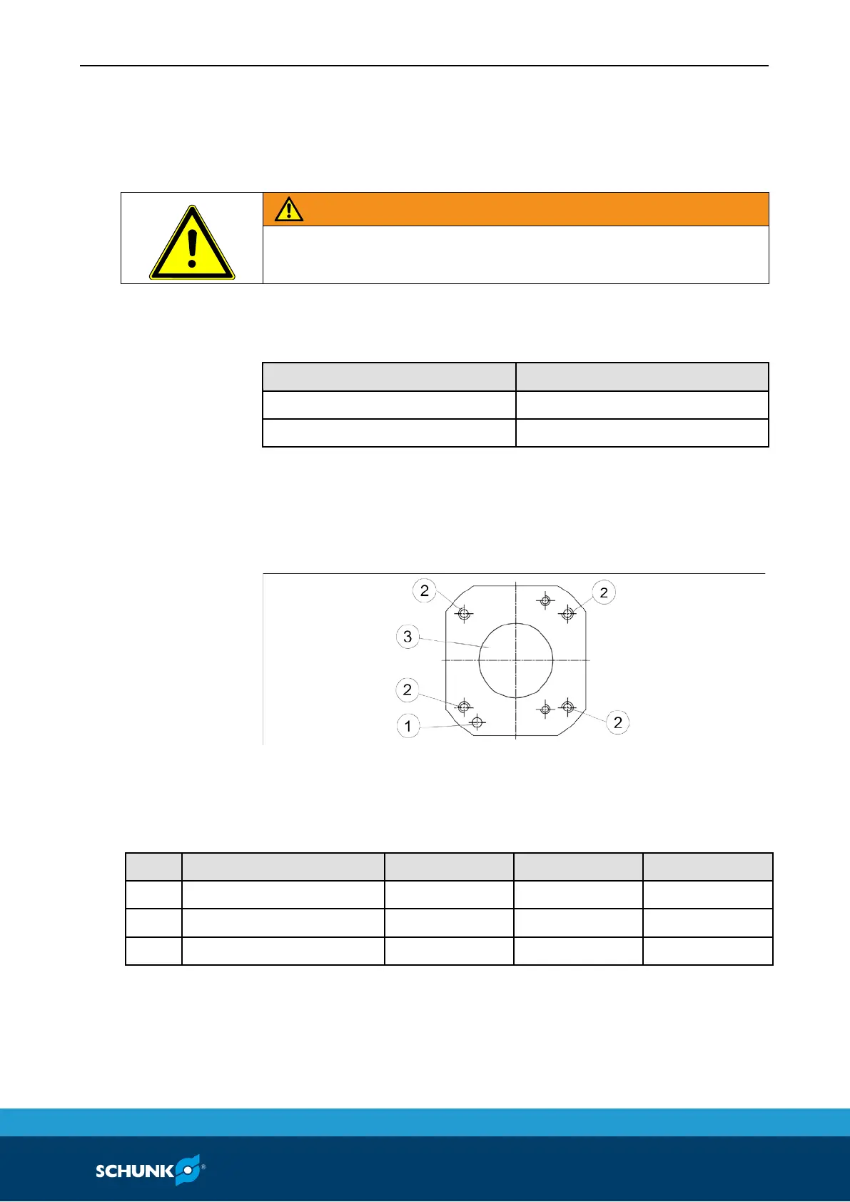
Fasten the gripper to the base surface using four threaded holes:
A centering bore and fixing bore are in the base surface in order to
position the gripper.
Fig. 1
Maximal screw-in depth of the fastening screws provided by the
customer.
Item Type 40 60 80
1 Mounting thread M4 (10 deep) M5 (14 deep) M6 (16 deep)
2 Centering bore Ø20H7 Ø25H7 Ø40H7
3 Fixing bore Ø4H7 Ø4H7 Ø5H7
7
7.1
of the bolting surface
Mounting
 Loading...