Assembly
02.02|PWG-S 40 - 80|en
17
The inductive proximity switches are electronic components,
which can react sensitively to high-frequency interference or elec-
tromagnetic fields.
• Check to make sure that the cable is fastened and installed cor-
rectly. Provide for sufficient clearance to sources of high-
frequency interference and their supply cables.
• Parallel switching of several sensor outputs of the same type
(npn, pnp) is permissible, but does not increase the permissible
load current.
• Note that the leakage current of the individual sensors (approx.
2 mA) is cumulative.
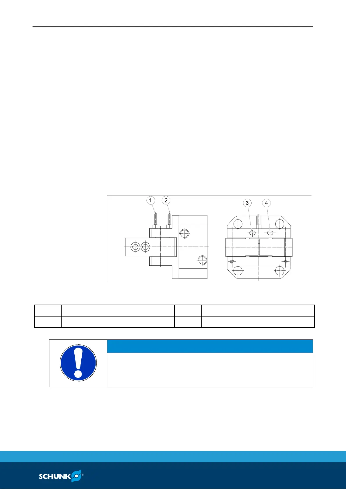
Assembly of the proximity switch
Fig. 7
1 Proximity switch "OPEN" 3 "OPEN" attachment screw
2 Proximity switch "CLOSED" 4 "CLOSED" attachment screw
NOTICE
Damage to the proximity switch during the assembly:
• Do not exceed the maximum tightening torque of the attach-
ment screw of 10 Ncm.
7.3.3
proximity switch

 Loading...