Assembly
16 02.02|PWG-S 40 - 80|en
The inductive proximity switches are electronic components,
which can react sensitively to high-frequency interference or elec-
tromagnetic fields.
• Check to make sure that the cable is fastened and installed cor-
rectly. Provide for sufficient clearance to sources of high-
frequency interference and their supply cables.
• Parallel switching of several sensor outputs of the same type
(npn, pnp) is permissible, but does not increase the permissible
load current.
• Note that the leakage current of the individual sensors (approx.
2 mA) is cumulative.
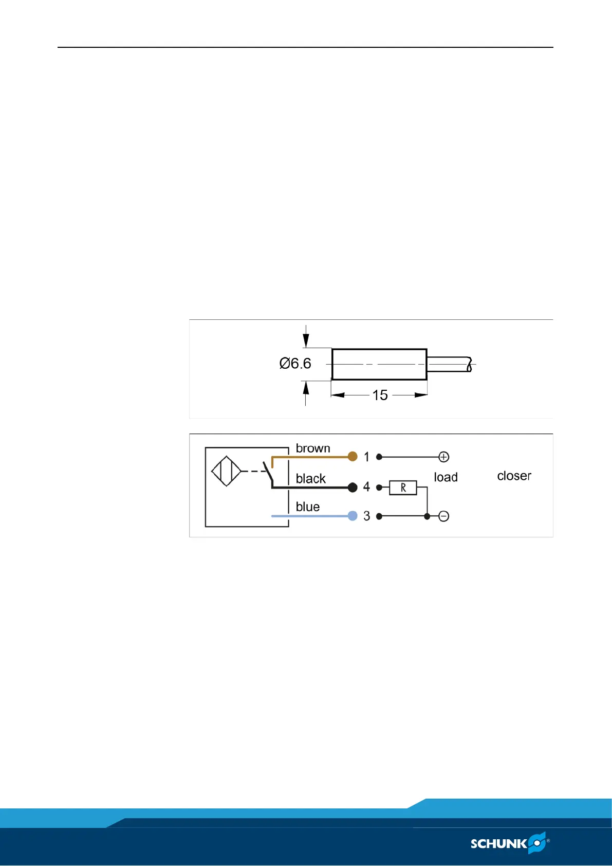
IN 60 inductive proximity switch
Fig. 5 IN 60 inductive proximity switch
Fig. 6
The inductive proximity switches used are equipped with reverse
polarity protection and are short-circuit-proof.
Make sure that you handle the proximity switches properly:
• Do not pull on the cable.
• Do not allow the sensor to dangle from the cable.
• Do not overtighten the mounting screw or mounting clip
• Please adhere to a permitted bend radius of the cable (☞ ca-
taolg).
• Avoid contact of the proximity switches with hard objects and
with chemicals, in particular nitric acid, chromic acid and sul-
phuric acid.
7.3.2

 Loading...