7
Stationary Air Compressor System Operating Instructions
General Description
The standard Stationary Air Compressor System is
equipped with a heavy-duty, three- or four-stage,
air-cooled compressor. The system also includes an
automatic condensate drain system, compressor stage
gauge panel, and a low oil shut-off switch. When properly
maintained, the air purication system is designed to
provide breathing air that meets Grade D/E of the CGA
breathing air standard G-7.1. Be sure you understand the
breathing air requirements and maintenance procedures
of your respiratory protection program.
Additional accessories available for the Stationary Air
Compressor System include a Cab Air cabinet enclosure,
choice of system controller, breathing air cylinder ll
station and compressed air storage cylinders.
2 - Features
These Operating Instructions apply to the following
SCOTT Breathing Air Compressor Systems:
The Simple Air Compressor Systems
5 HP 5000 psi Three Stage
7.5 HP 5000 psi Three Stage
7.5 HP 6000 psi Four Stage
10 HP 6000 psi Four Stage
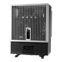
The HUSH Air Compressor System
20 HP 6000 psi Four Stage
15 HP 6000 psi Four Stage
Illustrations of the two compressors follow on the next
pages.
Routine Maintenance
The reliable operation of this equipment depends on
proper care and routine maintenance.
The operator must be trained by an authorized SCOTT
Safety technician in the proper operation of the
stationary breathing air system. The operator must read,
understand, and adhere to all safety precautions and
pre-operation tasks as described in this manual.
All scheduled maintenance beyond the scope of this
manual must be noted by the operator to be performed
by a SCOTT trained and certied service technician.
A Maintenance Record page is provided in this
instruction.
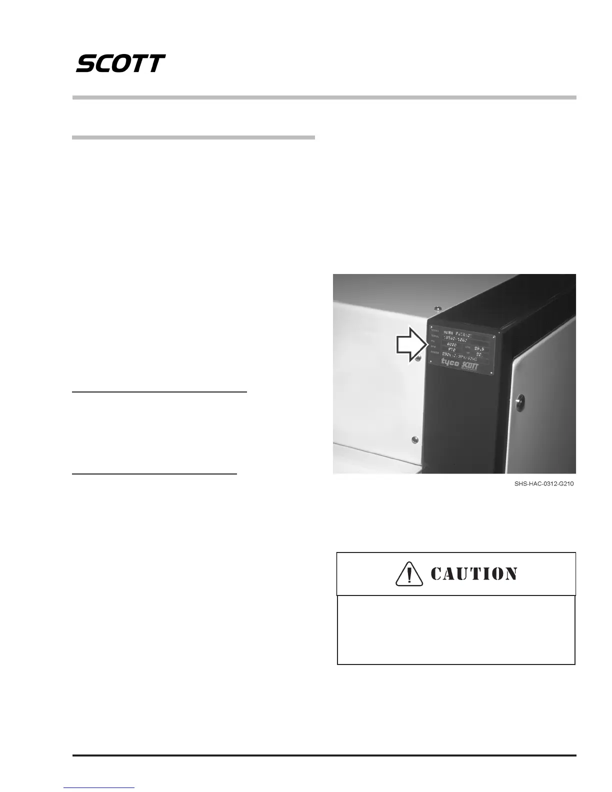
Compressor System Model Number
(Actual appearance and location may vary)
When ordering spare parts, note the unit model and
compressor serial number. This information will avoid
delays and the possibility of incorrect parts being
provided. The Stationary Air Compressor System model
number is stamped on the system identication tag. The
location of this tag will vary with the system model. The
compressor serial number is stamped on a metal plate
attached to the crankcase of the compressor.
Use only SCOTT approved parts and supplies
when servicing this compressor system. Use of
unapproved parts or supplies may result in reduced
performance or damage to the equipment.
To order replacement components, call 1-800-247-7257
or contact an authorized SCOTT Safety distributor.