HARRIER 3D Instruction Manual
15
CONTROL HORN INSTALLTION
1) Locate the two nylon control horns, two
nylon control horn backplates and four
machine screws.
2) Position the elevator horn on the both
side of elevator. The clevis attach- ment holes
should be positioned over the hinge line.
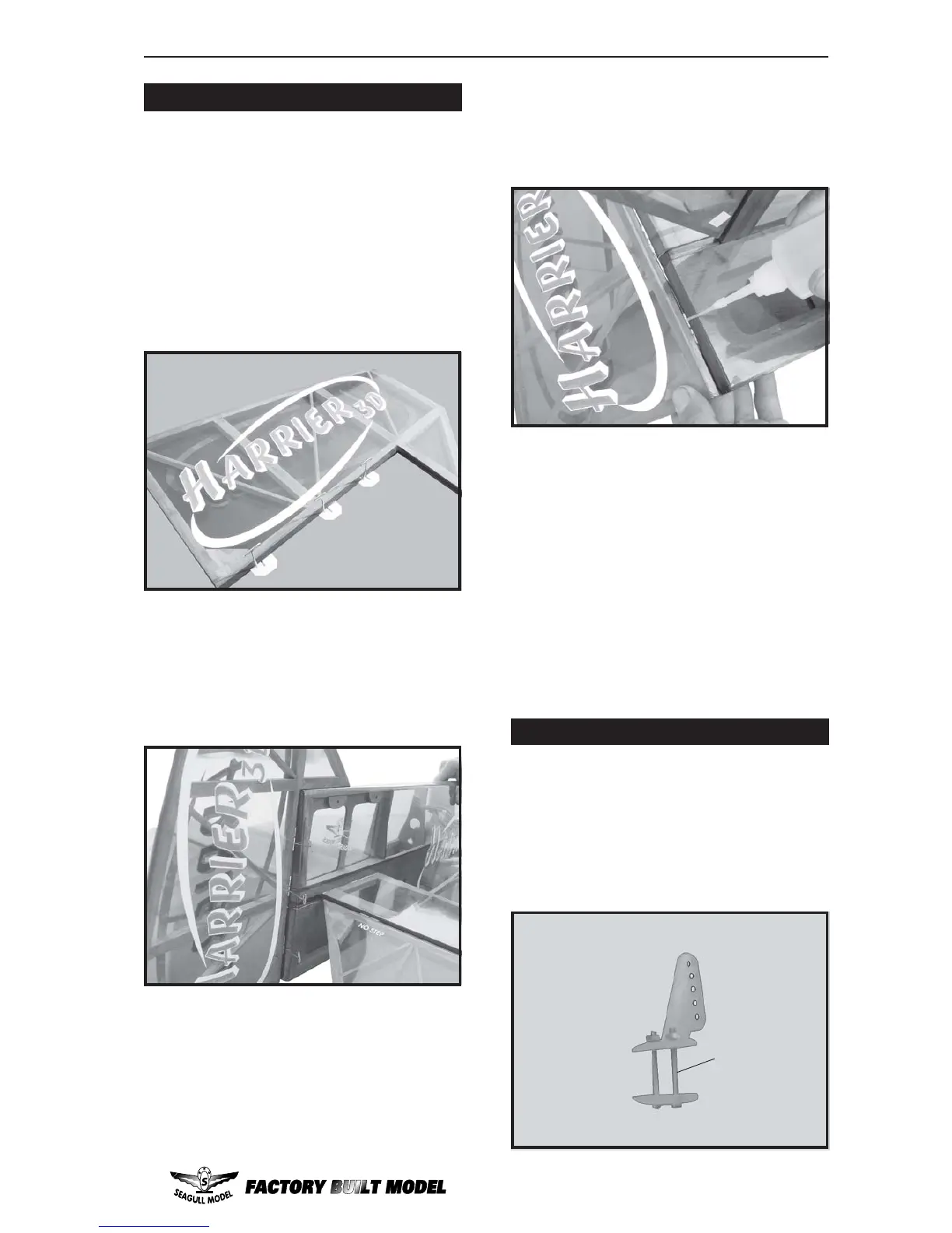
HINGING THE RUDDER
1) Carefully remove the rudder from one of
the fuselage panel. Note the position of the
hinges.
2) Remove each hinge from the fuselage
panel and rudder and place a T-pin in the center
of each hinge. Slide each hinge into the rudder
until the T-pin is snug against the rudder. This
will help ensure an equal amount of hinge is
on either side of the hinge line when the rudder
is mounted to the fuselage .
3) Slide the rudder on the fuselage panel
until there is only a slight gap. The hinge is
now centered on the fuselage panel and rudder.
Remove the T-pins and snug the rudder
against the fuselage panel. A gap of 1/64” or
less should be maintained between the
fuselage panel and rudder.
4)Deflect the rudder and completely
saturate each hinge with thin C/A glue. The
rudder front surface should lightly contact the
fuselage during this procedure. Ideally, when
the hinges are glued in place, a 1/64” gap or
less will be maintained throughout the lengh
of the rudder to the fuselage panel hinge line.
Note: The hinge is constructed of a special
material that allows the C/A to wick or penetrate
and distribute throughout the hinge, securely
bonding it to the wood structure of the fuselage
panel and rudder.
5) Turn the fuselage panel over and deflect
the rudder in the opposite direction from the
opposite side. Apply thin C/A glue to each
hinge, making sure that the C/A penetrates into
the rudder and fuselage panel.
6) Using C/A remover/debonder and a
paper towel, remove any excess C/A glue that
may have accumulated on the fuselage or in
the rudder hinge area.
Work the rudder up and down several
times to “work in” the hinges and check
for proper movement.
Note:
2MM x 20MM.
 Loading...