HARRIER 3D Instruction Manual
7
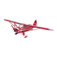
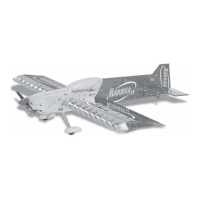
Because the size of servos differ,
you may need to adjust the size of
the precut opening in the mount. The
notch in the sides of the mount allow the
servo lead to pass through.
2) Install the aileron servo into the servo
mount, with the output shaft towards the lead-
ing edge of the wing, using the wood screws
provided with your radio system. Drill 1mm
pilot holes through the mount.
Repeat the procedure for the other wing
half.
AILERON LINKAGE
INSTALLING THE AILERON LINKAGE
1) Using a ruler & pen to draw a straight
line as below picture.
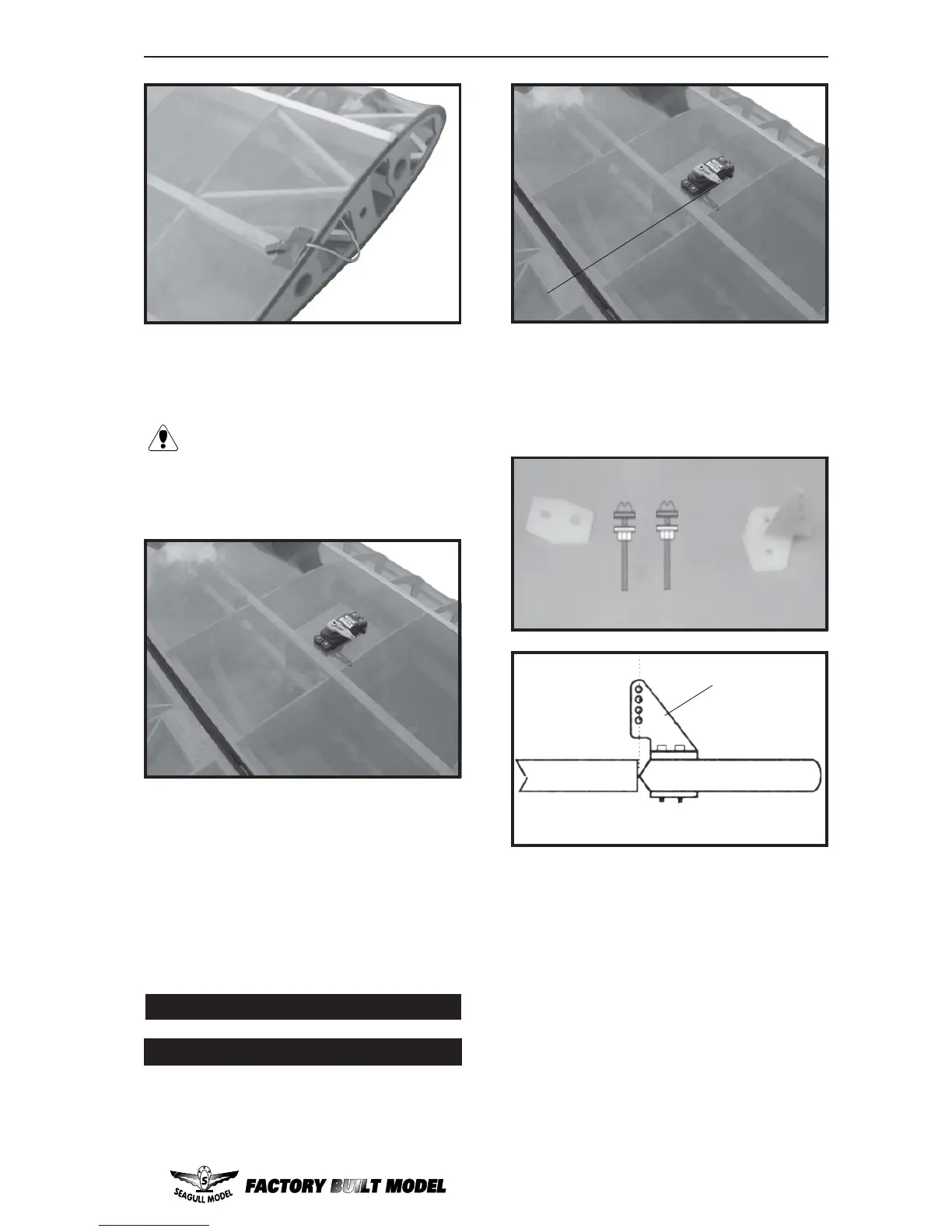
2) Locate the nylon control horns,nylon
control horn backplates and two machine
screws.
3) Position the aileron horn on the bot-
tom side of aileron. The clevis attachment
holes should be positioned over the hinge line.
4) Using a 1.5mm drill bit and the control
horns as a guide, drill the mounting holes
through the aileron halves.
6)Thread one nylon adjustable control
horn on to each aileron control rod. Thread
the horns on until they are flush with the ends
of the control rods.
5) Mount the control horns by inserting
the bolts through the control horn bases and
aileron halves, then into the mounting
backplates. Do Not overtighten the nuts or the
backplates may crush the wood.
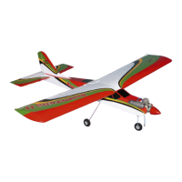
1) Install the rubber grommets and brass
collets onto the aileron servo. Test fit the servo
into the aileron servo mount.
(2) 2MMx30mm.
Control Horn.
Mounting Screws.
Mounting Plate.
Straight line.