21
Editing MHI Databases
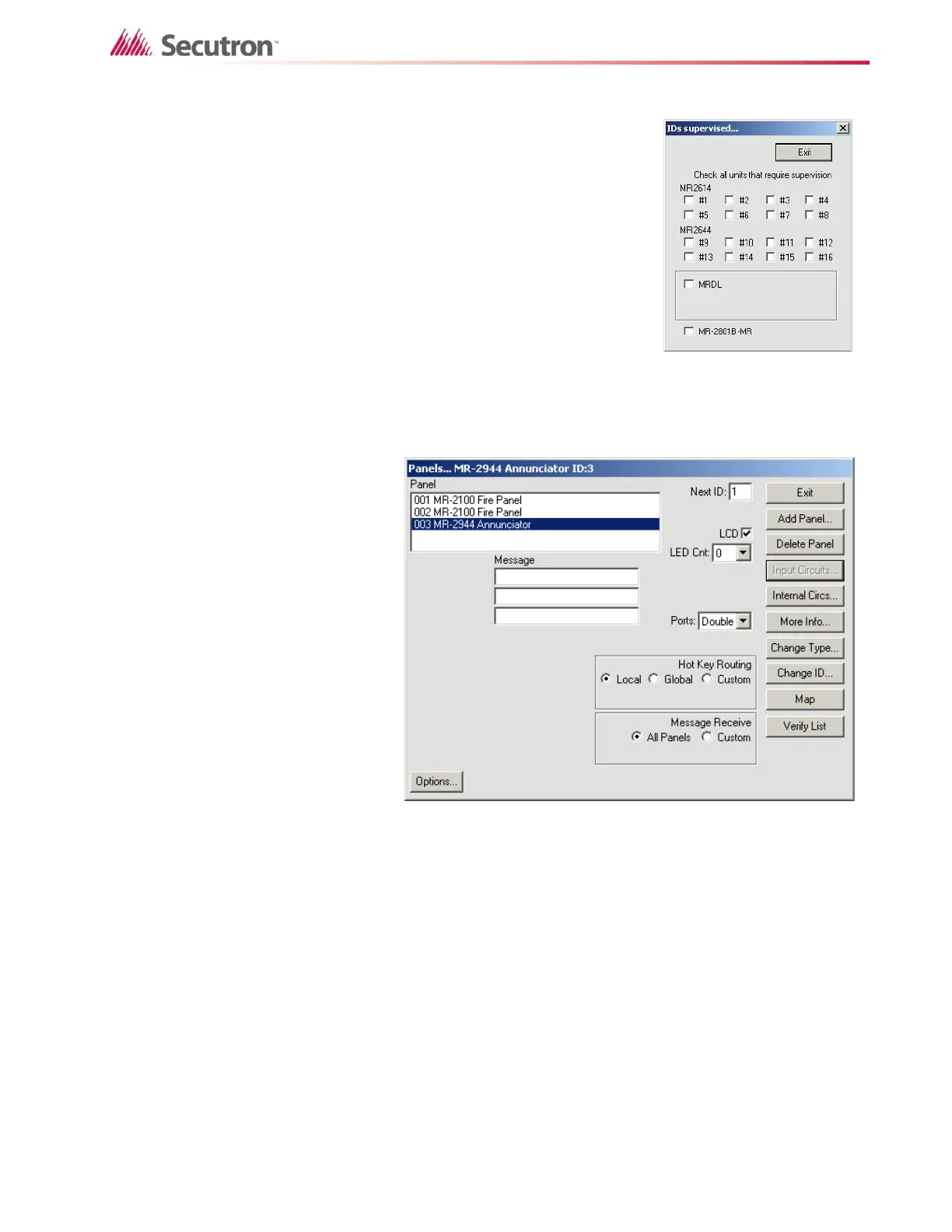
The IDs Supervised button displays all possible IDs of the
MR-2614 and MR-2644 annunciators (see Figure 9) as well
as the MR-2801B-MR and MRDL. Check the IDs that will be
connected to the system. When the MRDL is enabled, a
button will appear next to that option called Dialer Settings
(see the section on Dialer Options for a description of the
dialer options).
Hot Key Routing is a set of radio buttons for setting the other
panels or annunciators to be controlled by the current panel.
To have no other panels affected by the current panel, mark
Local. To have the current panel affect all other panels on the
network, mark Global. To choose only some panels, mark
Custom. A text entry box entitled route panel ids is then
displayed. Enter the panel IDs to be controlled separated by
commas, e.g. “2, 3, 4". Each ID listed will receive Hot Key
commands from the current panel whenever its Hot Keys are pressed.
Annunciators have the
following unique
controls for
programming (see
Figure 10).
The LCD check box is
located immediately
left of the buttons. It
indicates whether or
not the annunciator
has an alpha-numeric
LCD. This setting is
used by MHI only to
determine if the
Message Receive
check box should be
shown for the
annunciator in the
Relate Window. This
value is not sent to the
annunciator.
LED Count is located directly below the LCD check box. This defines the number of LED
zones the annunciator will be using. A count of zero will disable the Hot LEDs and Common
LED.
Hot LED is located directly below the LED Count drop down. This value defines the first of four
LED zones the annunciator will use for internal functions. Any of the zones can be chosen with
the requirement that there are four consecutive zones available. Entering a zone of 0 will
disable the hot key zones. These will reflect the current status of the annunciator and the
panel(s) it sends commands to.
Figure 10: Annunciator Panel Window