IN0016 Revision 12 Part # 004573 – 16 of 22
SP PRO Three Phase
Installation Notes
POWER PERFORMANCE PASSION
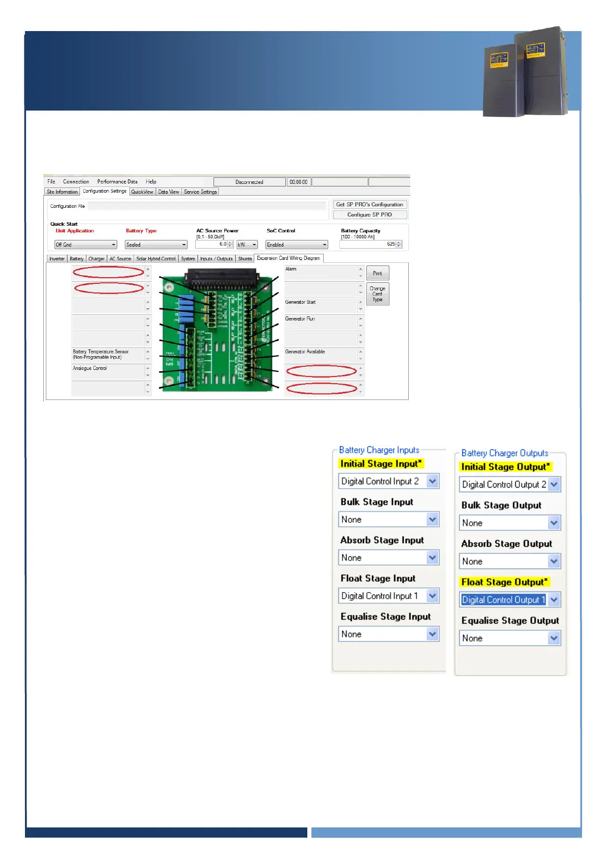
Select the
Configuration settings > Expansion card wiring diagram
menu and check Digital
control input 1, Digital control input 2, Digital control output 1 and Digital control output 2 are
not allocated to any functions. Their boxes should be blank (see diagram below).
Set the following Battery Charger Inputs and Outputs –
Initial Stage Input –
Digital Control Input 2
Initial Stage Edge –
Rising
Float Stage Input –
Digital Control Input 1 (default setting)
Float Stage Edge
Rising
Initial Stage Output –
Digital Control Output 2
Float Stage Output –
Digital Control Output 1
Test Linking (Test linking of charge stages)
With all SP PRO units configured, test Float link by briefly touching a link wire across Digital
Control Out 1 terminals. All SP PRO units should switch to the Float charge stage. Test Initial
link by briefly touching a link wire across Digital Control Out 2 terminals. All SP PRO units
should switch to the Initial charge stage.
This can be done on any of the phases.