IN0016 Revision 12 Part # 004573 – 13 of 22
POWER PERFORMANCE PASSION
SP PRO Three Phase
Installation Notes
SYNC Interface Connections
Each SP PRO must be interlinked via its SYNC interface. With reference to the diagram above
(
SYNC interface interconnections)
connect each SP PRO together via either SYNC1 or SYNC 2
connection using the supplied “network” type cables. Only two cables are required to connect
the three SP PRO units. Both SYNC1 and SYNC 2 connection points are the same and either
can be used.
Charge Stage Linking
In order for the SP PROs units to share the charging of the battery bank, it is necessary for the
charge stages to switch simultaneously. The charge stages are interconnected via wiring
between each of the SP PROs Expansion cards. Each Expansion Card is wired in the same
manner, then linked.
Signal power comes from one of the SP PROs 12V 1 amp output supplies (adjacent to the SYNC
1 connector within the SP PRO).
SP PRO Configuration – Additional Configuration Settings
The following settings are required to activate the three phase mode on the three SP PRO
inverters. It is good practise to start with the L1 Primary Phase as this will prevent false alarms
on the L2 and L3 Secondary phases while loading the configurations.
Turn on the pre-charge breaker or isolator for the system. When all three SP PRO inverters
power up, turn on the main battery isolators for all three SP PRO inverters.
NOTE: The SP PRO inverters may give “sync” errors until the main battery isolators have been
closed on all three SP PRO inverters.
LEAVE the SP PRO inverters in IDLE. All three phases must have their configuration
programmed before attempting to start the system from Idle mode to On mode.
It is required to create a separate SP LINK site file for each SP PRO phase and add the prefix
“L1”, “L2” or “L3” to the appropriate file.
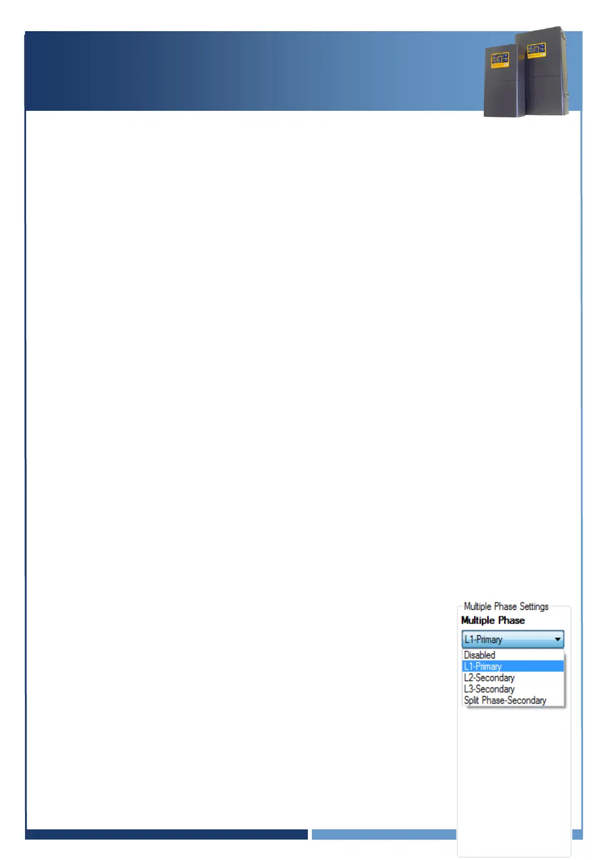
System – Multiple Phase Settings
Each SP PRO must be configured to suit the phase that is connected to by
setting the
Multi Phase
setting (Configuration Settings > System)
L1 – Primary: SP PRO is set as L1 phase – Red Phase
L2 – Secondary: SP PRO is set as L2 phase – White Phase
L3 – Secondary: SP PRO is set as L3 phase – Blue Phase
The
Split Phase – Secondary
and
Disabled
settings are not used in
a three phase system.