IN0016 Revision 12 Part # 004573 – 10 of 22
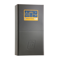
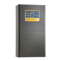
SP PRO Three Phase
Installation Notes
POWER PERFORMANCE PASSION
Installation
The SP PRO units are installed as per the installation instructions in the user manual.
Special attention needs to be paid to the minimum spacing between the SP PROs as outlined in
the Preparation section of the installation manual.
Place the supplied Phase labels (L1, L2 and L3) on the top right hand corner of each of the SP
PRO inverters. This will help to identify each inverter during system commissioning and testing.
AC Wiring
Attention must be paid to the Neutral conductor and connection through to the loads. The
neutral conductor connecting to the loads must be maintained such that operation of any
external SP PRO isolators would not alter the bonding between Neutral and Earth.
AC Source Neutral connections from L1, L2 and L3 must be connected together at the same
common point.
AC Load Neutral connections from L1, L2 and L3 must be connected together at the same
common point.
Three phase circuits which have loads that cannot tolerate a phase failure must be protected by
a Phase Failure Relay (not supplied).
Main DC Wiring
Refer to
SP PRO Three Phase main DC wiring layout
diagram above
L1, L2 and L3 phases must have their main negative battery connection wired in series with a
current shunt. The sense wires from the shunt are connected to the shunt inputs on the
expansion cards of the L1, L2 and L3 phase SP PROs. The
Shunt 1A
input of the expansion
card is to be connected to the SP PRO L1/L2/L3 side of the shunt. The
Shunt 1B
input of the
expansion card is to be connected to the battery side of the shunt. This enables all three
SP PROs to read the total battery current and keep track of the battery
State of Charge
(SoC).
If the system incorporates a DC charging source (such as DC coupled PV solar) then a separate
current shunt is needed. This current shunt is wired onto the inverter side of the battery shunt
with its sense wires connected to all three SP PROs (Shunt 2).
NOTE: With a DC charging source in the system the
Max Charge current
setting (Configuration
Settings > Charger) cannot exceed 200A.
Care must be taken to ensure that the cabling is rated to carry the current for the segment that
it is installed in. The negative connection from the shunt to the battery will be carrying the
combined current of three SP PRO inverters.