03
03
03
04
04~07
08
09
10
11
12
13
14
15
16
16
17
17
17
17
17
18
19
20
..........................
......................................
.................................
.......................................
..........................................................
.....................................................
..............................................
.....................................................
...........................................
...........................................................
..................................................
.......................................................
.....................................
...............................
.............................................
...............................................
..........................................
.................
............................................
..............................................................
............................
.............................................
................
Important Safety Advice
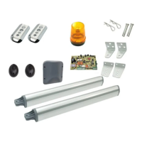
Content of the Kit
Connection Diagram
Installation Guide
Actuator
Control box
AC cable wiring
Transformer
Connection PCBA
Actuator
Warning light
Photocells
Function of photocells
Opening/Closing learning
Remote learning
Remote control
Auto close function
Manual gates control on the PCBA
Clear RF memory
Reset
Setting of the Dip Switches
Specifications
Declaration of CE Conformity
2
Content