A1.5 CHANGING MAIN BOARD SWITCH SETTINGS
A single bank of switches is located on the main circuit board near to the
large cylindrical capacitor. This bank contains 8 switches, labelled 1 to 8 on
the body.
One side of the switch block is marked OPEN, when this side of the white
rocker is down the switch is open, when it is up the switch is closed.
A1.6 SWITCH DESIGNATIONS
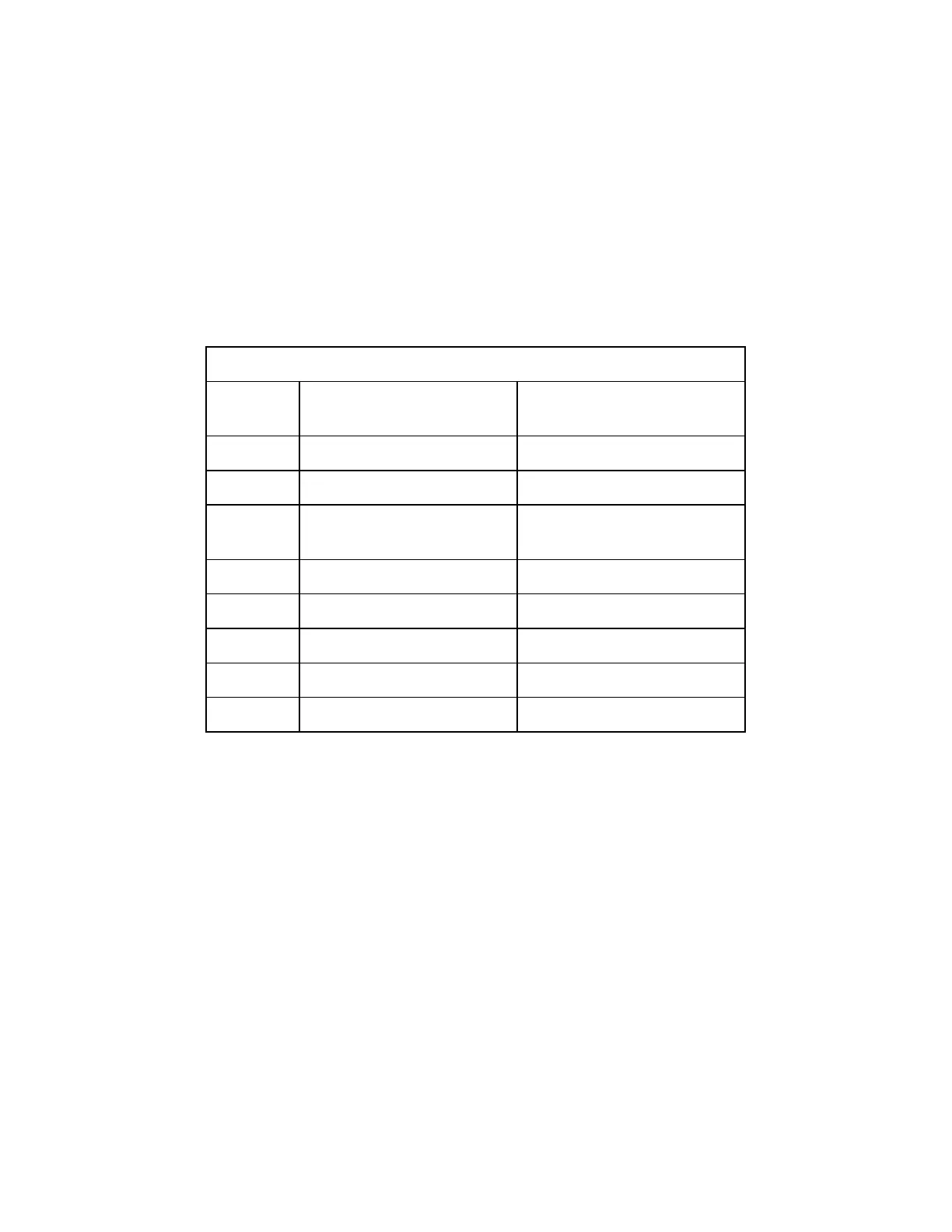
Main Circuit Board Switch Designations
Switch
Position
CLOSED
OPEN
1
Fixed Channel Mode
Custom Channel Mode
2
Computer Port = RS485
Computer Port = RS422
3
Computer Protocol =
Bi-Directional
Computer Protocol =
Uni-Directional
4
Multi-Point Calibration
Normal Calibration
5
Not Used
6
Not Used
7
Not Used
8
Not Used
A1.7 CHANGING UPPER BOARD SWITCH SETTINGS
Two banks of switches are used each with 8 positions. Both are mounted on
the upper (smaller) circuit board and are easily identified as rectangular red
blocks with 8 white switches. The switch block nearest to the cable entry and
fuses is switch block 2, the other of course being switch block 1. On each
switch block the individual switches are number 1 to 8.
One side of the switch block is marked OPEN, when this side of the white
rocker is down the switch is open, when it is up the switch is closed. It may
be necessary to use open or similar pointed instrument to operate the rocker.