VP400 Series Video Pro Form7343A Operation Manual
52
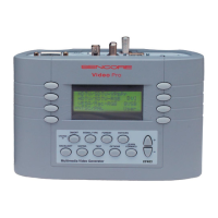
Figure 1. Connect the
RF test cable (39G189)
between the ATSC
output of the generator
and the ATSC input of
the receiver.
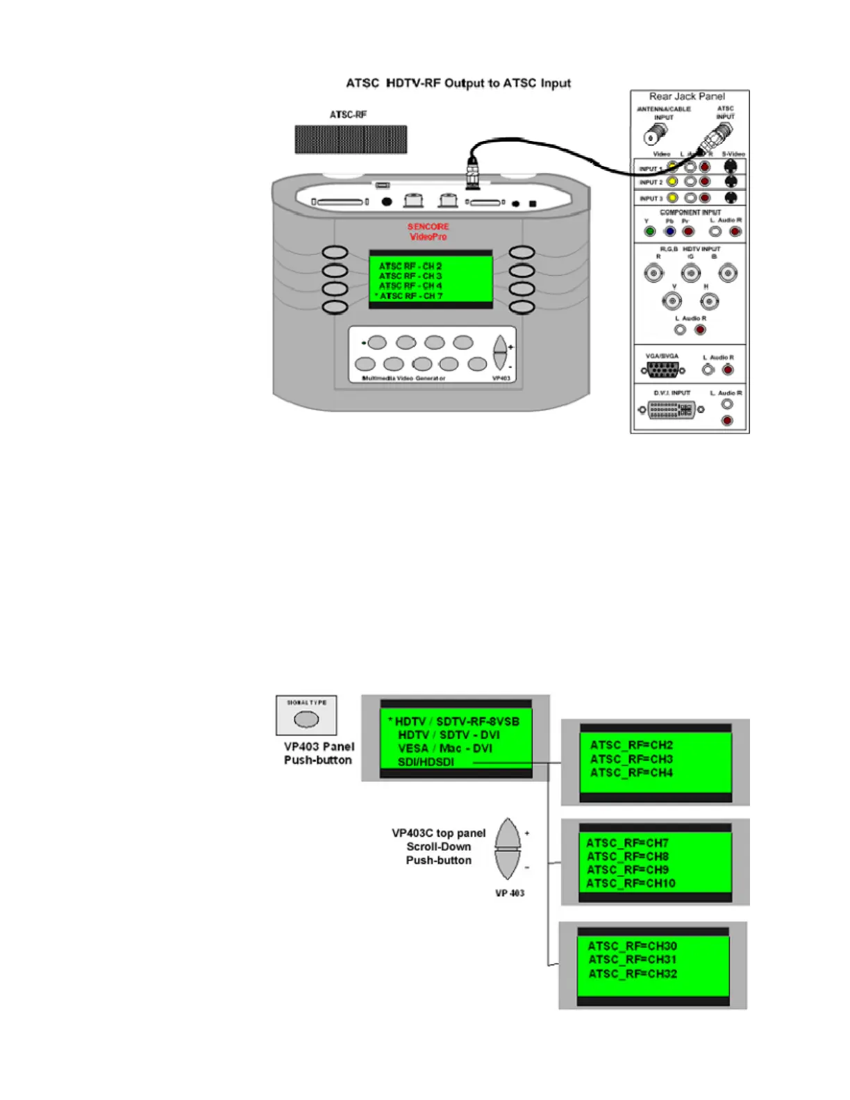
2. Select Signal Type & ATSC Channel
The moving video test clips are designed for output by the VP403C in the SDTV/HDTV RF
ATSC signal type. To select this signal on the VP403C press the “SIGNAL TYPE” pushbutton.
Push the “-” side of the large scroll-down button to increment to the second menu. Press the
button beside the display listing the SDTV/HDTV RF ATSC signal type.
Upon choosing this signal type, an ATSC RF channel menu appears. You may choose any RF
channel in the following ranges 2-4, 7-10, or 30-32. Use the scroll down pushbuttons to view the
menu pages providing these channel choices. Press the button beside the display for the desired
ATSC RF channel. After the channel selection the FORMAT menu(s) appear.
Figure 2. Select the
signal type
(HDTV/SDTV-RF-
8VSB) by pressing the
button beside this
display selection. An
ATSC RF channel
menu appears. Press
the button beside the
display for the desired
RF channel.
 Loading...