Installing the EM 300-500 G4
25
Installing the EM 300-500 G4
These sections contain detailed information about installing and starting
up the EM 300-500 G4.
You can find information about operating the EM 300-500 G4 under “Using
the EM 300-500 G4”.
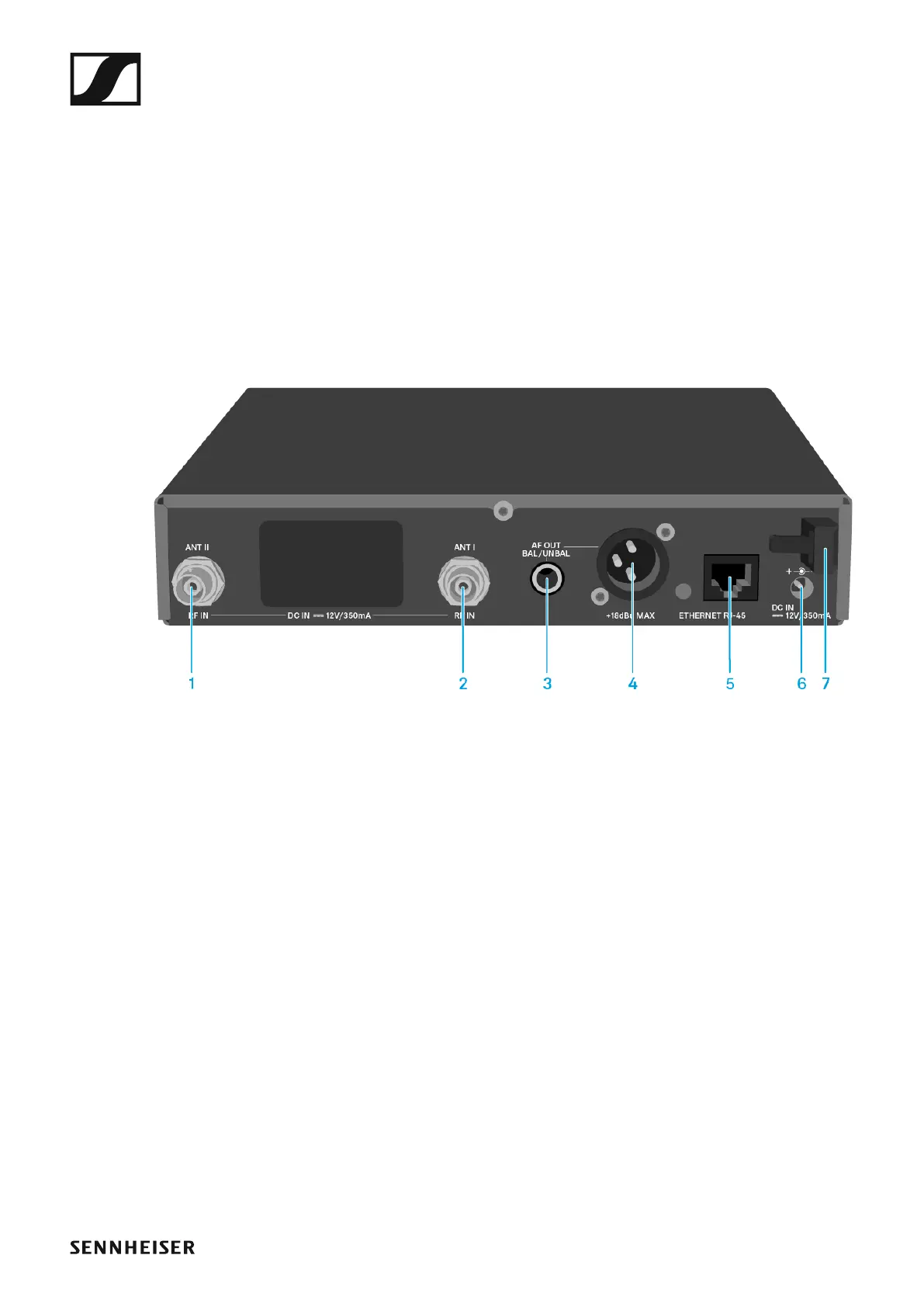
Connectors on the rear of the device
Product overview for the rear of the EM 300-500 G4
►
1 BNC socket, antenna input II (ANT II) with remote power supply unit
• See “Connecting antennas”
2 BNC socket, antenna input I (ANT I) with remote power supply unit
• See “Connecting antennas”
3 6.3 mm jack socket for audio output, unbalanced (AF OUT UNBAL)
• See “Outputting audio signals”
4 XLR-3 socket for audio output, balanced (AF OUT BAL)
• See “Outputting audio signals”
5 LAN connection socket (ETHERNET RJ 45)
• See “Creating a data network”
6 Connecting cables for the power supply unit (DC IN)
• See “Connecting/disconnecting the EM 300-500 G4 to/from the
power supply system”
7 Strain relief for the cable of the power supply unit
• See “Connecting/disconnecting the EM 300-500 G4 to/from the
power supply system”