METIS M308 / M309 / M313 / M316 / M318 / M323 / H309 / H316 / H318 (12-pin)
Electrical Connection
8
4 Electrical Connection
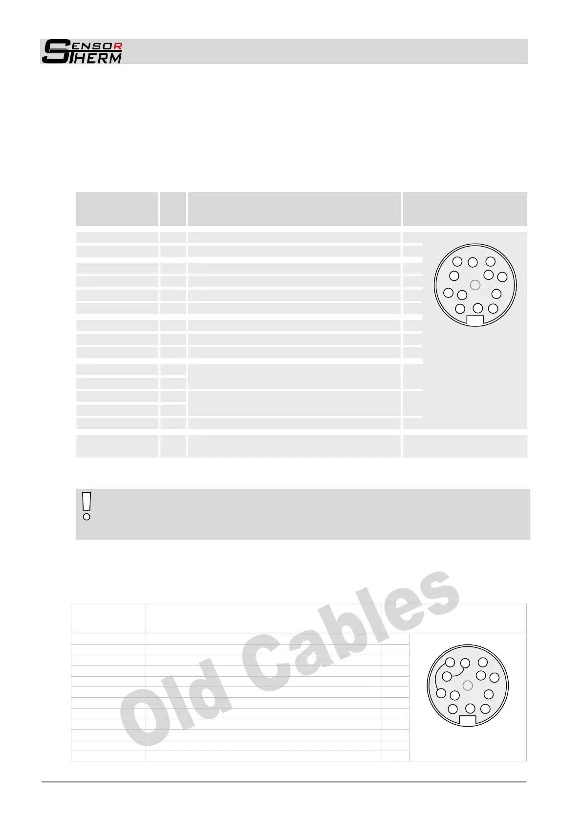
4.1 Cable Colors and Pin Assignment (14-wire connection cables)
The electrical connection of the pyrometer (supply voltage and measuring signal) will be done via the
connector on the rear panel. For this purpose, pre-assembled connection cables are available as ac-
cessories (see 9.4 Accessories). To prevent accidental short circuits, cable wires not in use should be
secured to the supplied screw terminals.
Cable colors
Sensortherm
pyrometers
+ 24 V DC power supply (18–30 V DC)
Connector pins
of the 12 pin
pyrometer connector
(view from outside)
0 V DC power supply (ground)
+ Analog output 1 (0 / 4–20 mA)
- Analog output 1 (0 / 4–20 mA)
+ Analog output 2 (0 / 4–20 mA)
- Analog output 2 (0 / 4–20 mA)
Digital input / output 1
1)
Digital input / output 2
1)
Digital input / output 3 / Analog input
1)
RS232: RxD
RS485: B (+)
2)
RS232: TxD
RS485: A (-)
2)
DGND (ground for interface)
Shield (connect only for cable extension,
do not connect in the control cabinet)
1)
Reference potential 0 V, brown
2)
H3 models only RS485
NOTE: In general we recommend the use of the current 14-wire connection cables.
Be careful when using an old 12-wire connector cables (before 2015):
Connection cable for the previous models Metis and Sirius cannot be connected without re-
strictions on a M3 / H3 pyrometer!
Old connection cables are bridged in the cable connector to pins E-C and D-F. Connecting such a ca-
ble to a M3 pyrometer, serial interface and analog output 2 and digital input / output 3 are connected
and the galvanic isolation between the outputs is bypassing. Thereby the pyrometer is not destroyed,
but the functions are no longer available. Using such a cable only analog output 1 is available as output.
Cable colors
old Sensor-
therm cable
Connector pins
cable socket (solder side)
Power supply 0 V DC (ground)
+ Analog output (0/4–20 mA)
- Analog output (0/4–20 mA)
Targeting light, external switch (bridge to K)
Maximum value storage, external clearing (bridge to K)
DGND (Ground for interface)
RxD (RS232) or B1 (RS485)
TxD (RS232) or A1 (RS485)
RxD (RS232) or B2 (RS485) (bridge to F)
TxD (RS232) or A2 (RS485) (bridge to C)
 Loading...