24 Appendix A: Basic Integration Guidelines
DUG-10009-01 RTM II FlexNet User Guide
A.4.2 Half Duplex (2-wire) RS-485 Communications
To connect an RTM II with optional RS-485 port to an IED with half duplex RS-485, place a jumper on the
RTM II RS-485 port between TX+ and RX+ and another jumper between TX- and RX-. Use the wiring
diagram below.
RTM II IED1 IED2+
TX+/RX+ + +
TX-/RX- - -
Gnd Gnd Gnd
A.4.3 Full Duplex (4-wire) RS-485 Communications
To connect an RTM II with optional RS-485 port to an IED with full duplex RS-485, use the wiring
diagram below.
RTM II IED1 IED2+
TX+ RX+ RX+
TX- RX- RX-
RX+ TX+ TX+
RX- TX- TX-
Gnd Gnd Gnd
A.5 Connect 10-29 VDC Power to RTM II
The RTM II needs 10-29 VDC, typically 170mA at 12 VDC, with a maximum of 0.6A. If you need data
reported, and the option to issue commands during a power outage, the RTM II power supply will need
battery backup. If you only have 120 VAC available, consider using an RTM II 120V model with built-in
battery backup.
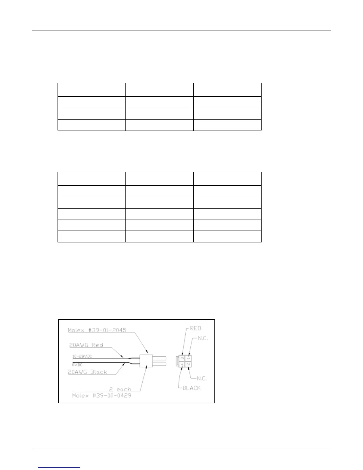
Many IEDs have options for a radio power supply outpu
t, generally between 10-29 volts, with battery
backup. Once you have located the power supply, hook the red power cable lead to +10 to +29 VDC and
the black power cable lead to 0 VDC.
Figure A-2: Cable Connections