38
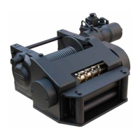
1.1.2 Double overcentre valve This allows the load to be spooled out at a
controlled rate. It also provides burst hose
protection. It is adjusted and sealed in our
factory.
1.1.3 Shuttle valve Supplies pressure for the spring loaded
brakes and the pressure gauge outlet on
the block.
1.1.4 Pressure gauge outlet R 1/4” female threaded connection.
1.2 Hydraulic motors
1.3 Hydraulic spring loaded
brake.
This automatically brakes the load when
the control valve is put in the neutral
position or if the oil pressure is lost.
2 Control valve unit
2.1 Directional control valve 4-way, 3 position with spring-centred
motorised spool and built-in pressure
reducing valve. The ports A and B must
have at least R 1/2” threaded connections
and the ports P and T at least R 3/4”.
2.2 Pressure reducing valve Must be pilot controlled, set to maximum
allowed pressure for the winch and be
sealed at installation.
3 Hydraulic oil supply unit
3.1 Hydraulic pump The pump must be able to deliver required
oil ow and oil pressure for the winch.The
pump is direct mounted to the vehicle PTO.
Fixed pump and load sensing or variable
pump requires different directional control
valve.
Winch basics