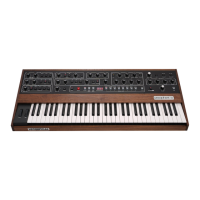
The
silver
knobs
(MASTER
TUNE and
VOLUME)
and
grey
switches (PROGRAMMER,
TUNE,
A-440,
SAVE
TO
TAPE
and LOAD
FROM
TAPE)
are not
programmable.
The
PITCH
and
MOD
wheels
are
also
not
programmable.
(The RECORD
switch is
orange
so
it
can
easily
be
distinguished.)
All
of
the
switches
except
BANK SELECT
have LED
indicators embedded
in
them.
And,
except
for
the
eight
PROGRAM
SELECTS,
SAVE
TO TAPE, LOAD
FROM
TAPE
and
TUNE,
all
LED
switches are
alternate
action:
one push turns them on,
the next
push
turns
them
off.
For
example, the
PRESET
switch
LED when
lit indicates
PRESET
Mode.
When
the
Prophet
is
switched to
MANUAL
Mode by
pushing the (lit)
PRESET
switch,
the
LED
goes off.
In
MANUAL
Mode
the control panel
always
indicates the
status of the patch
under
construction.
You
can see
exactly what
signal
paths are
closed
by (lit) switches.
The
knob
settings
reflect their actual
values.
Note
that
in
PRESET Mode as you
select
different
programs,
the switch LEDs
indicate
how the
switches are programmed.
But
there
is
no
way for
the knobs to move
themselves—
they just stay
where they
were last
set.
So,
in
PRESET Mode the
knobs do
not
normally
indicate their
"current"
setting.
However
as
soon as
you move
a
knob to
EDIT a
program, that
knob converts
to
MANUAL
operation.
So only the knobs
you
move will
actually
indicate their
current
setting:
the parameters
controlled by
unmoved knobs
do not change.
For example,
suppose you
like program
3-3
but want
to change
OSC A pitch and
prefer
a
brighter tone.
In PRESET Mode,
select
BANK
3-PROGRAM
3,
adjust OSC A
FREQUENCY to the
desired pitch and increase
the
FILTER CUTOFF to the desired
brightness.
You can cancel any
changes and
return
to
the original program by
hitting
PROGRAM SELECT 3. If you want to
permanently program location
3-3
to your
edited
version,
record it in
3-3.
Or, if both the original and the edited
version
are wanted,
record
the
edited program in a
new location (that
is, a
location with an
undesired
program).
For
a further discussion of
recording and
relocating programs,
see the notes following
programs
5-7
and
5-8, in
Section 8.
2-2
VOICE SIGNAL FLOW
The Prophet's audio
output results
from several stages of signal generation, combina-
tion, and
modification.
The front
panel is divided
into VOICE and
MODULATION
sections.
MODULATION
controls are
covered in paragraph
2-9.
It
should be kept
in
mind
that while
only one
voice is
depicted on the panel, the voice controls patch
five
voices
in parallel.
Figure
2-0
diagrams signal flow in
a
single voice. Basically,
the
MIXER
sets
OSCILLATOR
(VCO) A,
B,
and
NOISE levels sent
to the
FILTER
(VCF)
and
AMPLIFIER
(VCA) where,
roughly speaking, the timbre and dynamics are
shaped.
Finally
the voices are
combined and
the overall level
set by
the VOLUME control.
Each
voice module
is
detailed in
paragraphs
2-3
through
2-7.
2-2
CMIOOOD
2/82