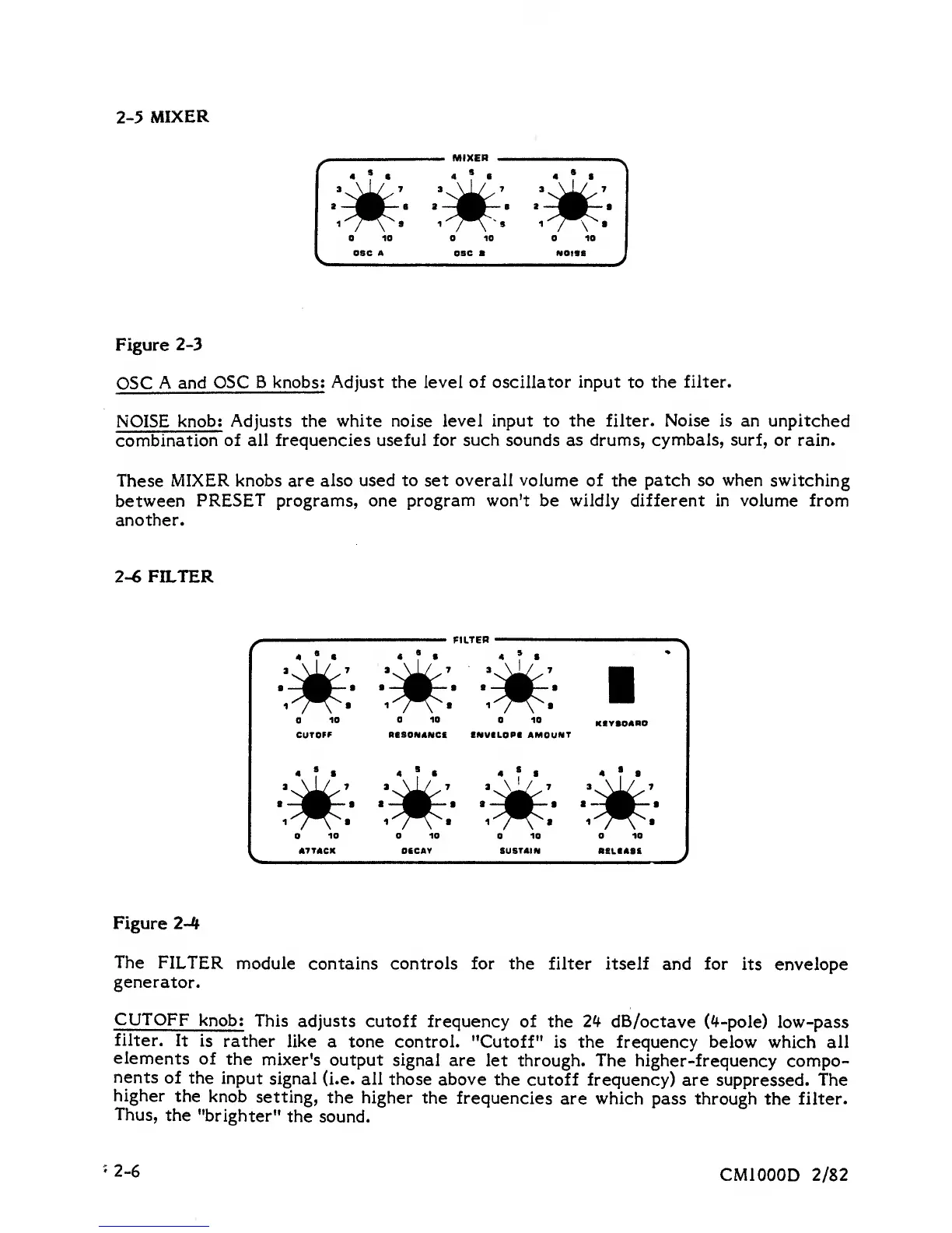
2-5 MIXER
MIXER
*
7
•
•
T
'
*
T
•
'v^' 'v^'
'.^^
I
—
^
—
s
a
—
^
—
2
—
j^
—
•
,-^.
^--^-s
1-^.
Figure
2-3
OSC
A and
OSC
B knobs; Adjust the level
of oscillator input
to
the filter.
NOISE
knob; Adjusts the
white noise level input to the filter.
Noise
is an unpitched
combination
of all frequencies useful
for such sounds as drums, cymbals, surf, or
rain.
These
MIXER knobs are also
used to set overall volume of the patch so when switching
between
PRESET programs, one program won't be wildly different in volume from
another.
2-6
FILTER
FILTEP
I
—
^^
—
• I
—
j^
—
I a
—
^
—
^H
1^;^^.
1^"^:^.
i^^^»
^
10
CUTOFF RESOMANCC EMVELOPI AMOUNT
•?•
*?•
*?•
•?•
'X^'
'^^^
»X^^ 'X^'
a
—
j^
—
•
a
—
j^
—
a
a
—
j^
—
a
a
—
j^
—
a
i'''^^a
^^^^»
i^^^«
^^^^*
10
ATTACK
10
OECAV
10
SUSTAIN
10
RELEASE
Figure
2-4
The
FILTER
module
contains
controls
for the filter itself
and
for
its envelope
generator.
CUTOFF
knob;
This adjusts
cutoff frequency of
the
24
dB/octave
Cf-pole) low-pass
filter.
It
is
rather like
a tone control.
"Cutoff" is the frequency below
which
all
elements
of
the
mixer's
output signal
are
let through. The higher-frequency
compo-
nents
of
the input
signal
(i.e. all those
above
the cutoff frequency)
are suppressed. The
higher
the knob
setting,
the higher the
frequencies
are which
pass through
the
filter.
Thus,
the
"brighter"
the
sound.
2-6
CMIOOOD
2/82