AL-2020/2035/2040/2050/2060 ADJUSTMENTS 9 - 4
4) If the measurement value is out of the specified range, change
the set value and repeat the adjustment procedure.
The default value is 50.
Note: The rear edge void cannot be checked with the first sheet
after entering the simulation mode, the first sheet after turn-
ing off/on the power, or the first sheet after inserting the
cassette. Use the second or later sheet to check the rear
edge void.
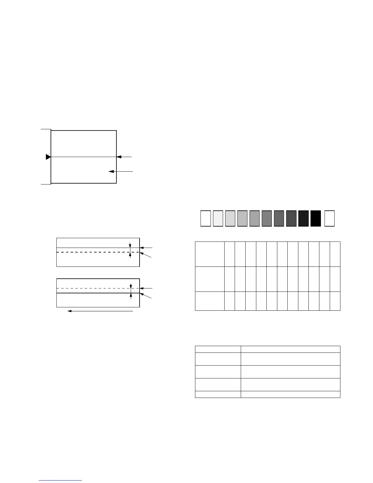
(3) Center offset adjustment
1) Set the self-made test chart for the center position adjustment
so that its center line is aligned with the center mark of the doc-
ument guide.
• Test chart for the center position adjustment.
Draw a line at the center of A4 or 8 1/2" x 11" paper in the paper
transport direction.
2) Execute SIM 50-10 to select the print center offset (cassette
paper feed) adjustment mode.
The set adjustment value is displayed on the copy quantity dis-
play.
3) Make a copy and check that the copied center line is properly
positioned.
The standard value is 0 ± 2mm from the paper center.
4) If the measured value is out of the specified range, change the
set value and repeat the adjustment procedure.
When the set value is increased by 1, the copy image is
shifted by 0.1mm toward the rear frame.
• For the manual paper feed, change the manual paper feed
adjustment mode and perform the similar procedures.
• Since the document center offset is automatically adjusted by
the CCD which scan the reference lines (F/R) on the back of
document guide, there is no need to adjust manually.
2. Copy density adjustment
A. Copy density adjustment timing
The copy density adjustment must be performed in the following
cases:
• When maintenance is performed.
• When the developing bias/grid bias voltage is adjusted.
• When the optical section is cleaned.
• When a part in the optical section is replaced.
• When the optical section is disassembled.
• When the OPC drum is replaced.
• When the main control PWB is replaced.
• When the EEPROM on the main control PWB is replaced.
• When the memory trouble (U2) occurs.
B. Note for copy density adjustment
1) Arrangement before execution of the copy density adjustment
• Clean the optical section.
• Clean or replace the charger wire.
• Check that the voltage at the high voltage section and the devel-
oping bias voltage are in the specified range.
C. Necessary tool for copy density adjustment
• One of the following test charts:
UKOG-0162FCZZ, UKOG-0089CSZZ, KODAK GRAY SCALE
• B4 (14" x 8 1/2") white paper
• The user program AE setting should be "3."
Test chart comparison table
D. Features of copy density adjustment
For the copy density adjustment, the image data shift function pro-
vided in the image process LSI is used.
List of the adjustment modes
Document guide
Center
Copy paper
(A4 or 8 1/2″ × 11″)
(Copy A)
(Copy B)
2.0mm or less
2.0mm or less
Copy image
Copy paper
folding line
Copy image
Copy paper
folding line
Shift
Shift
(Paper feed direction)
UKOG-
0162FCZZ
DENSITY
No.
12345678910W
UKOG-
0089CSZZ
DENSITY
No.
0.1 0.2 0.3 0.5 1.9 0
KODAK
GRAY
SCALE
123419A
Auto mode Brightness 1 step only
Manual mode Brightness 5 steps. Adjustment of only the
center brightness is made.
Photo mode Brightness 5 steps. Adjustment of only the
center brightness is made.
Manual T/S mode Brightness 5 steps. Adjustment of only the
center brightness is made.
T/S Auto mode Brightness 1 step only
1 10
W
23456789