CD-BA3100
– 20 –
43 44
41
33
32
47
46
28
10
Mark position
11
45
42
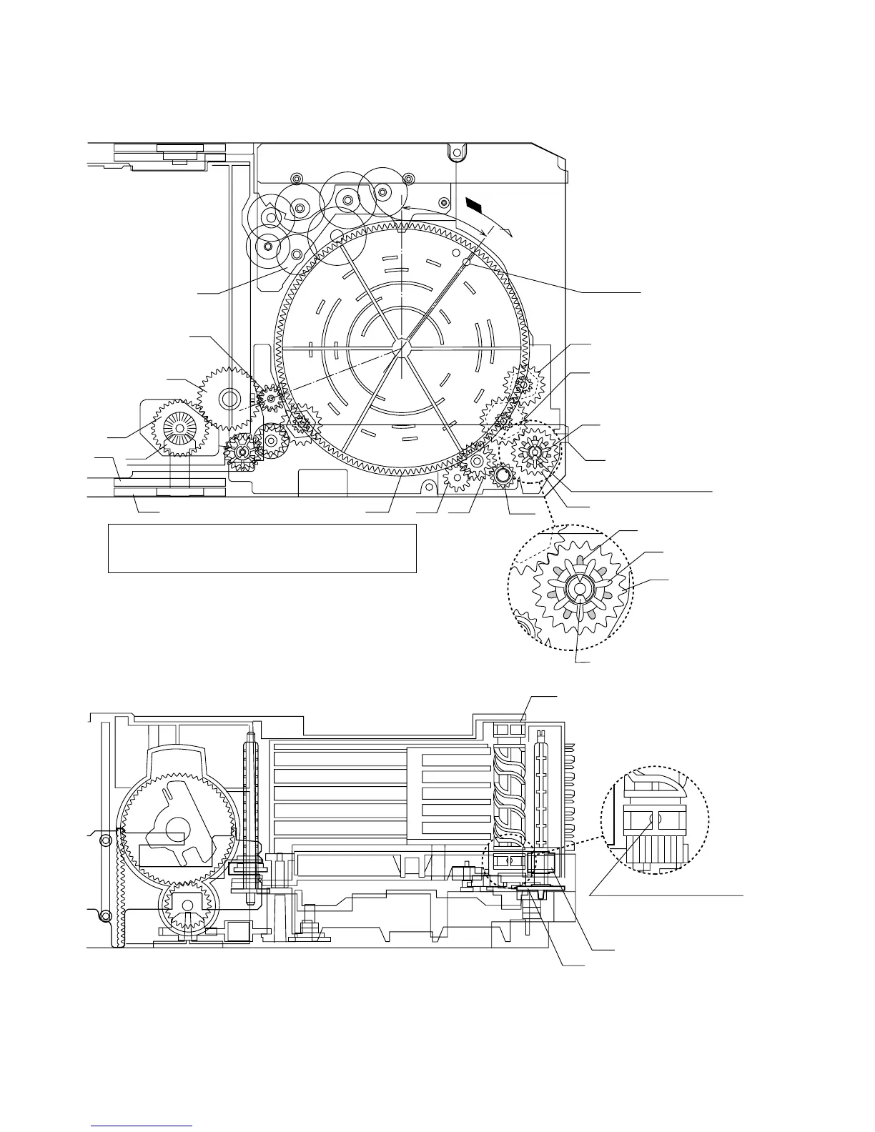
LIFT GEAR A
30
TRAY DRIVE GEAR F
35
TRAY JOINT GEAR F
35
TRAY JOINT GEAR F
02
CHANGE BOX L
*1
30
TRAY DRIVE GEAR F
40
LIFT CAM
40
LIFT CAM
30
TRAY DRIVE GEAR F
35
TRAY JOINT GEAR F
37°
*2
TRAY JOINT GEAR F
(CHANGE BOX L ASS'Y) ASSEMBLING POSITION
LIFT CAM
Direct the recess part (trapezoidal side)
of the axis 35 in this direction.
Assembling procedure
1. Turn the mode big gear approx. 37 degrees in the arrow direction.
2. Assemble the change box L ass'y.
Note: At this time, the tray joint gear F must be located in the position shown in figure.
Moreover, the gear must be engaged securely.
3. After assembly, return the mode big gear to the initial position.
4. Assemble the lift cam.
Note: At this time, the lift cam (No.40) must be located in the position shown in figure 20.
Scale: 2 magnifications
*1: To position the axis part
of 35, engage it with 33.
*2: When it is aligned as
described in *1, the hatched part
(low gear-height part of gear)
will be positioned as shown.
Since this gear engagement is not
visually checked, verify that it does
not float when the gear box L is installed.
Scale: 2 magnifications
During assembly, make the
O part visible in this direction.
Note: Among 4 ribs on the
circumference, one rib alone
is provided with O.
Figure 20