LC-32L400M
2 – 1
LC-32L400M
Service Manual
CHAPTER 2. OPERATION MANUAL
[1] OPERATION MANUAL
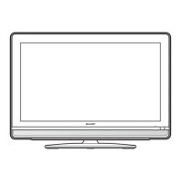
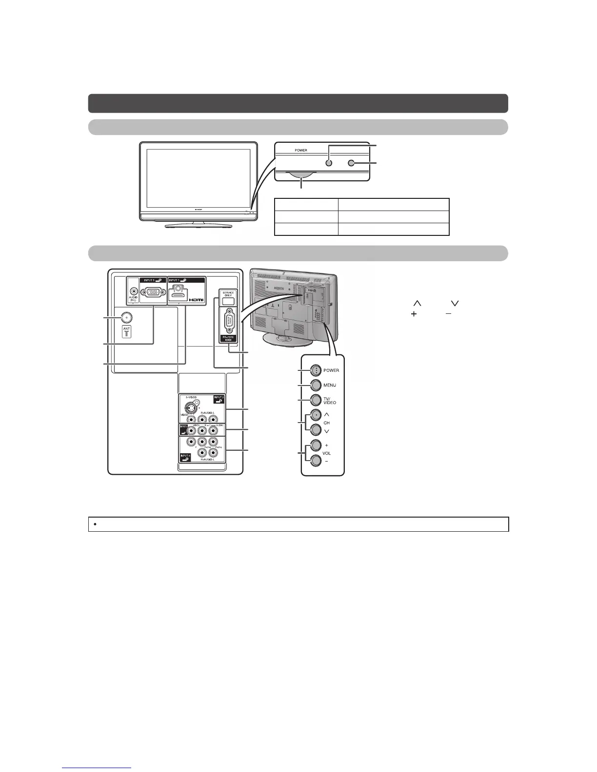
Part names
TV (Front)
Remote control sensor
OPC sensor
POWER indicator
Light off Power off
Lighted (Red) The TV is in standby mode.
Lighted (Green) The TV is on.
TV (Rear)
ANALOGUE RGB (PC)
6
9
11
8
7
10
12
13
1
2
3
4
5
1 POWER (On/Off) button
2MENUbutton
3 TV/VIDEO button
4 Channel up ( )/down ( ) buttons
5 Volume up ( )/down ( ) buttons
6 Antenna input terminal
7 INPUT 5 (PC) terminals*
8 INPUT 1 (HDMI) terminal*
9 RS-232C terminal
10 SERVICE ONLY terminal**
11 INPUT 2 terminals
12 INPUT 3 terminals
13 INPUT 4 terminals
* The INPUT 1 and INPUT 5 terminals can both use the same audio input terminal. However, the proper item must be
selected in the "PC Audio Select" menu.
**Usually do not connect anything to this terminal as it is reserved only for service personnel.
The illustrations in this operation manual are for explanation purposes and may vary slightly from the actual operations.