LC-52XS1E/RU/LC-65XS1E/RU
5 – 8
9. IC6351 (RH-iXC012WJQZQ)
This is an IC for IrSS encoding, which receives the signals from the IrSS light receiving section located on the RC/LED PWB, encode them and
transfer the data to IC6201 via the SLOW BUS.
Ir communication controller
B7, A8, F7, E8 UDQS, UDQS
LDQS, LDQS
I/O Data Strobe : Output with read data, input with write data.
Edge-aligned with read data, centered in write data.
For the x16, LDQS corresponds to the data on DQ0~DQ7 ; UDQS corresponds to
the data on DQ8~DQ15
The data strobes DQS, LDQS and UDQS may be used in single ended mode or paired with optional
complementary signals DQS, LDQS and UDQS to provide differential pair signaling to the system dur-
ing both reads and writes. An EMRS(1) control bit enables or disables all complementary data strobe
signals.
A2, E2, L1, R3,
R7, R8
NC - No Connect : No internal electrical connection is present.
A9, C1, C3, C7,
C9, E9, G1, G3,
G7, G9
VDDQ - DQ Power Supply : +1.8V ±0.1V.
A7, B2, B8, D2,
D8, E7, F2, F8,
H2, H8
VSSQ - DQ Ground.
J1 VDDL - DLL Power Supply : +1.8V ± 0.1V.
J7 VSSDL - DLL Ground.
A1, E1, J9, M9,
R1
VDD - Power Supply : +1.8V ±0.1V.
A3, E3, J3, N1,
P9
VSS - Ground.
J2 VREF I Reference voltage for inputs for SSTL interface.
Pin No. Pin Name I/O Pin Function Remarks
J8 CI I Oscillation buffer input Duty 40-60%
J9 CO O Oscillation buffer output
H7,J7 CLKSEL[1:0] I Clock selection
00-16MHz 01-24MHz 10-32MHz 11-48MHz
A9 XRESET I Reset signal Negative logic
H6, J6,
H5, J5,
H4, J4, J3,
J2, J1, H1,
G1, F1,
E2, E1,
D2, D1
D[15:0] I/O System Data Bus
C1, B1,
A1, A2,
A3, B3
A[5:0] I System Address Bus
A5 XCS I System Chip Select Negative logic
A6 XRD I System Read signal Negative logic
A7 XWR I System Wright signal Negative logic
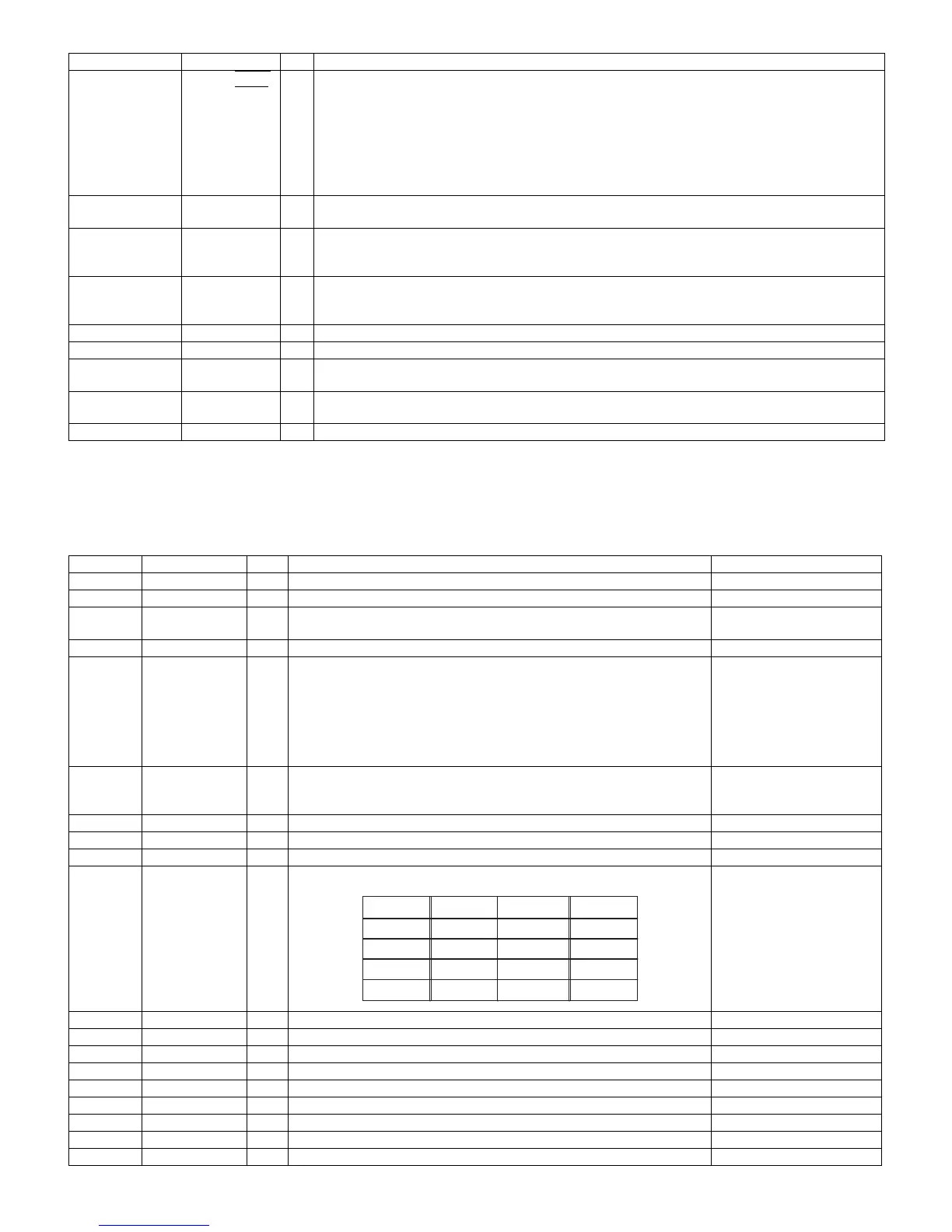
A4 BYTE I System 8bit access
Positive logic
A8 INT O System Interrupt request signal Logic is a register setup.
B5 DREQ O System DMA Transmission demand signal Logic is a register setup.
B4 XDACK I System DMA Transmission bitter taste knowledge signal Negative logic
E9 IRTXA O Front end Channel A transmission signal Positive logic
D9 IRRXA I Front end Channel A received signal Logic is a register setup.
G9 IRTXB O Front end Channel B transmission signal Positive logic
F9 IRRXB I Front end Channel B received signal Logic is a register setup.
F8 IRRX2 I Front end Channel received signal Logic is a register setup.
C9 IRRC O Front end Ir remote control signal Positive logic
Pin No. Pin Name I/O Pin Function
BYTE A[0] D[1 5:8] D[7:0]
0 0 Effective Effective
0 1 Effective Invalid
1 0 Invalid Effect ive
1 1 Effective Invalid
 Loading...