LC-52XS1E/RU/LC-65XS1E/RU
5 – 9
10.IC6608 (VHiBR24L64F-1Y)
This is an EEPROM, in which the portion of the data processed by the IC6201 is stored.
11.IC6651 (VHi29GL064N-1Q)
This is a 64Mb NOR flash, in which the software of IC6201 is stored.
64M FLASH MEMORY
12.IC6652 (RH-iXC623WJQZQ)
This is a 1Gb NAND flash, in which the IC6201’s data and the preinstalled pictures of the wall picture function are stored.
1Gb FLASH MEMORY
B9 SD O Front end shutdown signal Positive logic
B7 TXD O The transmitting data signal of UART Positive logic
B8 RXD I The receiving data signal of UART Positive logic
H9 TEST I Test Mode Usual '0' Fixation
C8, G2,
G8
VDDIO - I/O Power Supply (1.8-3.3v)
B2, E8, H3 VDDCORE - Core power supply (1.8V)
B6, C2,
D8, F2,
H2, H8
VSS - Ground
Pin No. Pin Name I/O Pin Function
3-12,15, 18-26,
31,54
A21-A0 I 22 Address inputs
35-42, 44-50 DQ14-DQ0 O 15 Data input/output
51 DQ15/A-1 O DQ15 (Data input/output, at LSB word mode), A-1(LSB-Address Input, at byte mode)
32 CE# I Chip Enable input
34 OE# I Output Enable input
13 WE# I Write Enable input
16 WP#/ACC I Hardware Write Protect input/Programming Acceleration input
14 RESET# I Hardware Reset Pin input
17 RY/BY# I Ready output ; indicates the status of the Burst read./Busy output
53 BYTE# I Selects 8-bit or 16-bit mode
43 VCC - Device Power supply (3.0V)
33, 52 VSS - Device Ground
1, 2, 27, 28, 30,
55, 56
NC - Pin Not Connected Internally
29 VIO - Output Buffer Power
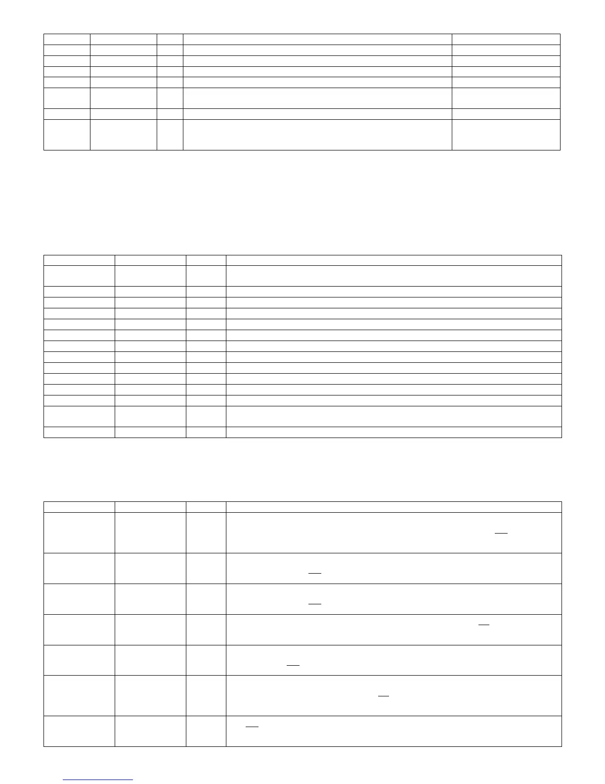
Pin No. Pin Name I/O Pin Function
29-32, 41-44 IO7 - IO0 O Data Inputs / Outputs
The IO pins allow to input command, address and data and to output data during read / pro-
gram operations. The inputs are latched on the rising edge of Write Enable (WE
). The I/O
buffer float to High-Z when the device is deselected or the outputs are disabled.
16 CLE O COMMAND LATCH ENABLE
This input activates the latching of the IO inputs inside the Command Register on the Rising
edge of Write Enable (WE
).
17 ALE ADDRESS LATCH ENABLE
This input activates the latching of the IO inputs inside the Address Register on the Rising
edge of Write Enable (WE
).
9 CE# I CHIP ENABLE
This input controls the selection of the device. When the device is busy CE
low does not dese-
lect the memory.
8 WE# I WRITE ENABLE
This input acts as clock to latch Command, Address and Data. The IO inputs are latched on
the rise edge of WE
.
18 RE# I READ ENABLE
The RE input is the serial data-out control, and when active drives the data onto the I/O bus.
Data is valid tREA after the falling edge of RE
which also increments the internal column
address counter by one.
19 WP# I WRITE PROTECT
The WP pin, when Low, provides an Hardware protection against undesired modify (program /
erase) operations.
Pin No. Pin Name I/O Pin Function Remarks
 Loading...