MX-5001N ADJUSTMENTS 5 – 37
[Check Method 2]
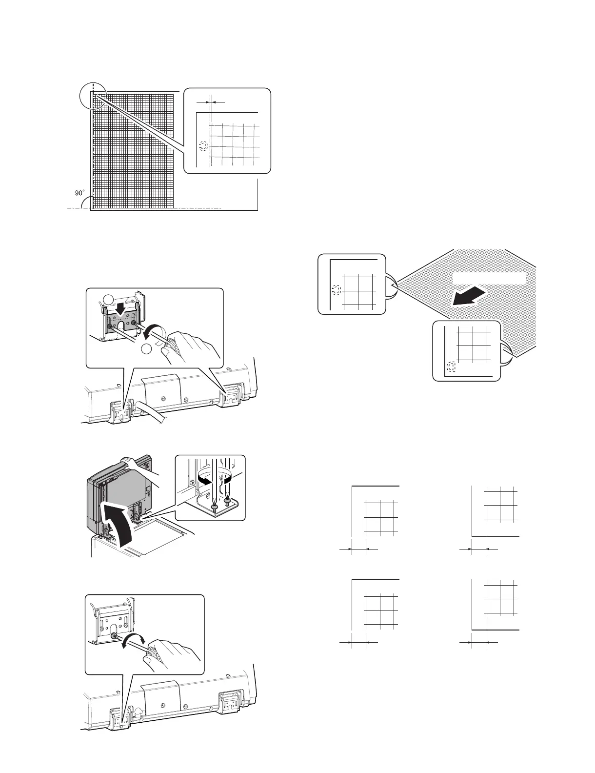
Check that the squareness of the main scanning direction
print line for the longitudinal direction of paper is within
1.0mm.
If the front surface copy image is as shown above and the
back surface copy is not as shown above, go to the step 3)
of "3. Skew adjustment (Back surface mode)."
If the above requirement is not met for the paper's front side,
then do step 3.
3) Loosen the hinge screws and lower the two attachments.
4) Open the DSPF and loosen the screw.
5) Adjust by turning the DSPF skew adjusting screw on the right
side of the DSPF rear frame.
[When the main scanning direction print line is shifted to the
left]
If a < b, then turn counterclockwise the DSPF skew
adjusting screw.
[When the main scanning direction print line is shifted to the
right]
If a > b, then turn clockwise the DSPF skew adjusting screw.
Repeat steps 2 to 5 until an acceptable result is obtained.
(Skew adjustment (back surface mode))
This adjustment is needed in the following situations:
* The DSPF section has been disassembled.
* When replacing the DSPF unit.
* The DSPF unit generates skewed scanned images.
1) Create an adjustment chart by printing in duplex mode the self-
print pattern 1 (grid pattern) specified in Simulation 64-1.
Make sure that the print grid pattern is almost in parallel with
the paper edges, and apply position marks 'A', 'B', 'C' and 'D' to
the leading and trailing edges of the paper for both front and
back sides of the paper.
2) Copy the adjustment chart (created in step 1) to A3 (11" x 17")
paper in DSPF duplex mode, and then check the image for
skews (Set in the DSPF feed tray so that the mark on the
adjustment chart is at the edge).
• Check with one of the following methods.
[Check Method 1]
A
0 - 1.0mm
1
2
A
B
Paper pass direction
A
B
a
b
C
D
c
d
(Front side)
Make sure that the output satisfies the condition:|a-b|±1mm
(Back side)
Make sure that the output satisfies the condition:|c-d|±1mm
 Loading...