MX-5001N ADJUSTMENTS 5 – 47
ADJ 18 Copy image position,
image loss adjustment
18-A Copy image position, image loss
adjustment (Document table mode)
This adjustment is needed in the following situations:
* When the scanner (reading) section is disassembled.
* When the scanner (reading) unit is replaced.
* When the LSU is replaced or removed.
* When the registration roller section is disassembled.
* U2 trouble has occurred.
* The PCU PWB has been replaced.
* The EEPROM of the PCU PWB has been replaced.
* The scanner control PWB has been replaced.
* The EEPROM on the scanner control PWB has been replaced.
NOTE: Before executing this adjustment, be sure to confirm that
the ADJ 17 Print area (Void area) adjustment (Print engine
section) has been completed normally.
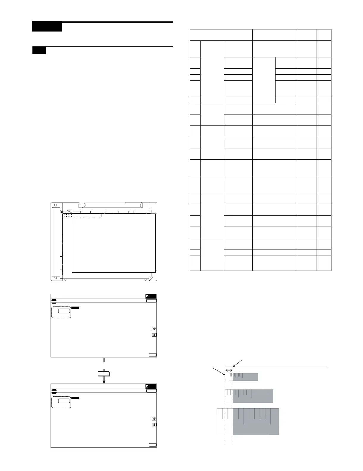
1) Place a scale on the document table as shown in the figure
below.
Place a scale so that it is in parallel with the scanning direction
and that its lead edge is in contact with the document guide
plate.
Place white paper on the document table so that the scale lead
edge can be seen.
2) Go through the modes specified in Simulation 50-1.
3) Set RRCA, LEAD, and SIDE to the default values.
4) Perform the image lead edge reference position adjustment.
Press [CLOSE] key, and shift from the simulation mode to the
copy mode and make a copy in 100% mode and in 200%
mode.
When the adjustment value of RRCA is proper, the lead edge
image from 3.0mm is not copied in either of 100% and 200%
copy scale.
If not, change and adjust the RRCA value.
(Adjust so that the lead edge image from 3.0mm is not copied
in either of different copy magnification ratios.)
Repeat the above procedures until a satisfactory result is
obtained.
10 20 30 40 50 60 70 80 90 100110 120 130 140 150
OK
㪈㪇㪄㫂㪼㫐
ǂǂǂ6,08/$7,21ǂǂ12
&/26(
7(67
/($'('*($'-8670(179$/8(
$˖
˷˹
˖55&$
$˖
˖55&%&6
%˖
˖55&%&6
&˖
˖55&%/&&
'˖
˖55&%$'8
)˖
˖55&%0)7
(˖
˖/($'
*˖
˖6,'(
+˖
˖'(1$
,˖
˖'(1%
-˖
˖)52175($5
.˖
2.
ǂǂǂ6,08/$7,21ǂǂ12
&/26(
7(67
/($'('*($'-8670(179$/8(
$˖
˷˹
˖55&$
$˖
˖55&%&6
%˖
˖55&%&6
&˖
˖55&%/&&
'˖
˖55&%$'8
)˖
˖55&%0)7
(˖
˖/($'
*˖
˖6,'(
+˖
˖'(1$
,˖
˖'(1%
-˖
˖)52175($5
.˖
2.
Display/Item Content
Setting
range
De-
fault
A Lead
edge
adjust-
ment
value
RRCA Document lead edge
reference position
(OC)
0 - 99 50
B RRCB-CS12
Resist
motor ON
timing
adjust-
ment
Standard
Tray
1 - 99 50
C RRCB-CS34 Desk 1 - 99 50
D RRCB-LCC LCC 1 - 99 50
E
RRCB-MFT Manual
paper
feed
1 - 99 50
F RRCB-ADU ADU 1 - 99 50
GImage
loss area
setting
value
LEAD Lead edge image
loss area setting
0 - 99 30
H SIDE Side image loss area
adjustment
0 - 99 20
I Void area
adjust-
ment
DENA Lead edge void area
adjustment
1 - 99 30
J DENB Rear edge void area
adjustment
1 - 99 30
K FRONT/
REAR
FRONT/REAR void
area adjustment
1 - 99 20
L Off-center
adjust-
ment
OFSET_OC OC document off-
center adjustment
1 - 99
50
M Magnifica
tion ratio
correction
SCAN_
SPEED_OC
SCAN sub scanning
magnification ratio
adjustment (CCD)
1 - 99 50
N
Sub
scanning
direction
print area
correction
value
DENB-MFT Manual feed
correction value
1 - 99 50
O
DENB-CS1 Tray 1 correction
value
1 - 99
50
P
DENB-CS2 Tray 2 correction
value
1 - 99
50
Q
DENB-CS3 Tray 3 correction
value
1 - 99
50
R
Sub
scanning
direction
print area
correction
value
DENB-CS4 Tray 4 correction
value
1 - 99
50
S DENB-LCC LCC correction value 1 - 99 50
T
DENB-ADU ADU correction value 1 - 99 50
100%
200%
Paper lead
edge
Scale image 3.0mm position
5mm 10mm
5mm
10mm
 Loading...