MX-5001N ADJUSTMENTS 5 – 46
4) Check the adjustment pattern to confirm that the items below
are in the range of the standard values.
If the above condition is not satisfied, or if it is set to a desired
condition, execute the simulation 50-1.
(Note) Feed paper from all the paper feed trays to confirm.
5) Go through the modes specified in Simulation 50-1.
6) Select the adjustment item I, J, K with the scroll key, and enter
the adjustment value and press [OK] key.
When the adjustment value is increased, the void area is
increased. When the adjustment value is decreased, the void
area is decreased.
When the adjustment value is changed by 1, the void area is
changed by 0.1mm.
NOTE: The adjustment value and the actual void area are related
as follows:
Adjustment value/10 = Actual void area
NOTE: When the amount of the rear edge void is different between
each paper feed tray, change the adjustment value of item
N, O, P, Q, R, S, T (DENB-XXX) in SIM50-1 and adjust.
The adjustment item J (DENB) have a effect on the paper
of all paper feed tray.
That is, adjustment value of item N, O, P, Q, R, S, T
(DENB-XXX) fine adjusts to adjustment item J (DENB) for
each paper tray.
After execution of the above, perform procedures 1) - 4) to check
that the void area is within the specified range.
Though the lead edge void area adjustment value is proper, if the
lead edge void area is not within the specified range, change the
adjustment value of RRCB-XXX (item B, C, D, E, F) of SIM 50-1.
Repeat the above procedures until a satisfactory result is obtained.
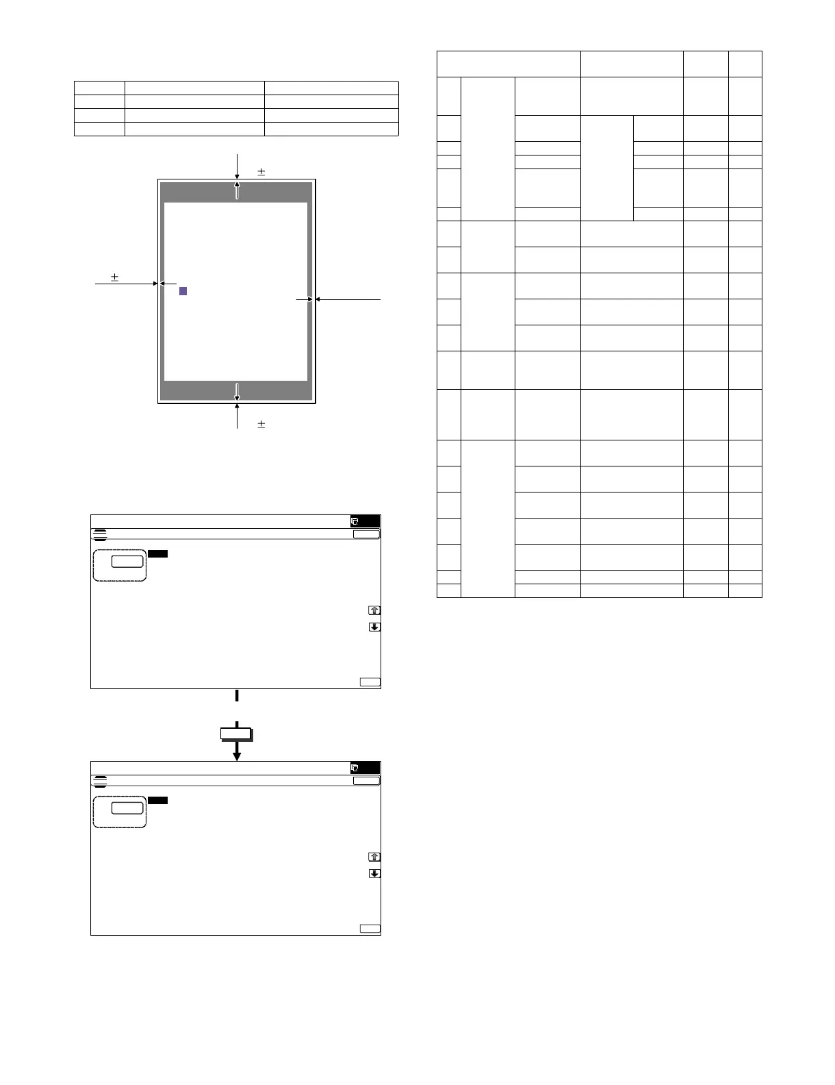
Content Standard adjustment value
X Lead edge void area 3.0 ± 1.0mm
Y Rear edge void area 2.0 - 5.0mm
Z1/Z2 FRONT/REAR void area 2.0 ± 2.0mm
X
Y
Z2
2.0
3.0 1.0mm
2.0 - 5.0mm
Z1
2.0
2.0mm
2.0mm
OK
10-key
ǂǂǂ6,08/$7,21ǂǂ12
&/26(
7(67
/($'('*($'-8670(179$/8(
$˖
˷˹
˖55&$
$˖
˖55&%&6
%˖
˖55&%&6
&˖
˖55&%/&&
'˖
˖55&%$'8
)˖
˖55&%0)7
(˖
˖/($'
*˖
˖6,'(
+˖
˖'(1$
,˖
˖'(1%
-˖
˖)52175($5
.˖
2.
ǂǂǂ6,08/$7,21ǂǂ12
&/26(
7(67
/($'('*($'-8670(179$/8(
$˖
˷˹
˖55&$
$˖
˖55&%&6
%˖
˖55&%&6
&˖
˖55&%/&&
'˖
˖55&%$'8
)˖
˖55&%0)7
(˖
˖/($'
*˖
˖6,'(
+˖
˖'(1$
,˖
˖'(1%
-˖
˖)52175($5
.˖
2.
Display/Item Content
Setting
range
De-
fault
A Lead
edge
adjust-
ment
value
RRCA Document lead edge
reference position
(OC)
0 - 99 50
B RRCB-CS12 Resist
motor ON
timing
adjust-
ment
Standard
Tray
1 - 99 50
C RRCB-CS34 Desk 1 - 99 50
D RRCB-LCC LCC 1 - 99 50
E RRCB-MFT Manual
paper
feed
1 - 99 50
F RRCB-ADU ADU 1 - 99 50
GImage
loss area
setting
value
LEAD Lead edge image
loss area setting
0 - 99 30
H SIDE Side image loss area
adjustment
0 - 99 20
I Void area
adjust-
ment
DENA Lead edge void area
adjustment
1 - 99 30
J DENB Rear edge void area
adjustment
1 - 99 30
K FRONT/
REAR
FRONT/REAR void
area adjustment
1 - 99 20
L Off-center
adjus-
tment
OFSET_OC OC document off-
center adjustment
1 - 99 50
M Magnifi-
cation
ratio
correction
SCAN_
SPEED_OC
SCAN sub scanning
magnification ratio
adjustment (CCD)
1 - 99 50
NSub
scanning
direction
print area
correction
value
DENB-MFT Manual feed
correction value
1 - 99 50
O DENB-CS1 Tray 1 correction
value
1 - 99 50
P DENB-CS2 Tray 2 correction
value
1 - 99 50
Q DENB-CS3 Tray 3 correction
value
1 - 99 50
R DENB-CS4 Tray 4 correction
value
1 - 99 50
S DENB-LCC LCC correction value 1 - 99 50
T DENB-ADU ADU correction value 1 - 99 50
 Loading...