Parity/Overflow
Flag
This flag
is
set
to
a
particular
state depending on the
operation
being performed.
For
arithmetic
operations, this flag indicates
an
overflow
condition
when the result in the
Accumulator
is
greater
than the
maximum
possible
number
(+127)
or
is
less
than the
minimum
possible
number
(-128).
This
overflow
condition
can
be
determined
by
examining
the sign bits
of
the operands.
For
addition,
operands
with
different
signs
will
never
cause
overflow.
When adding operands
with
like
signs and
the result
has
a
different
sign, the
overflow
flag
is
set.
For
example:
+120=01111000
+105
=
0110
1001
+225
11100001
ADDEND
AUGEND
(-95)
SUM
The
two
numbers added
together
has
resulted
in
a
number
that
exceeds
+127
and the
two
positive operands
has
resulted in a nagative
number
(-95)
which
is
incorrect.
The
overflow
flag
is
therefore set.
For
subtraction,
overflow
can occur
for
operands
of
unlike
signs. Operands
of
like
sign
will
never cause
overflow.
For
example:
+127
(-)
-64
+191
01111111
1100
0000
10111111
MINUEND
SUBTRAHEND
DIFFERENCE
The
minuend
sign
has
changed
from
a positive
to
a negative, giving
an
incorrect
difference.
Overflow
is
therefore
set.
Another
method
for
predicting
an
overflow
is
to
observe the carry
into
and
out
of
the sign
bit.
If
there
is
a carry
in and
no
carry
out,
or
if
there
is
no
carry in and a carry
out,
then
overflow
has
occured.
This flag
is
also used
with
logical operations and rotate
instructions
to
indicate the
parity
of
the result. The
number
of
'1'
bits in a
byte
are
counted.
If
the
total
is
odd,
'ODD'
parity
(P=O)
is
flagged.
If
the
total
is
even,
'EVEN'
parity
is
flagged
(P=1
).
During
search
instructions
(CPI, CPIR, CPD, CPDR) and
block
transfer
instructions
(LDI,
LDIR,
LDD,
LDDR)
the
P/V
flag
monitors
the state
of
the
byte
count
register (BC). When decrementing, the
byte
counter
results in a
zero
value,
the
flag
is
reset
to
0, otherwise the flag
is
a Logic
1.
During
LD
A,
I and
LD
A,
R
instructions,
the
P/V
flag
will
be
set
with
the
contents
of
the
interrupt
enable
flip-flop
(1
FF2)
for
storage
or
testing.
When
inputting
a
byte
from
an
1/0 device, IN r, (C), the flag
will
be
adjusted
to
indicate the
parity
of
the data.
The
Half
Carry Flag (H)
The
Half
Carry Flag (H)
will
be
set
or
reset depending on the carry and
borrow
status between bits 3 and 4
of
an
8-bit
arithmetic
operation.
This flag
is
used by the decimal adjust
accumulator
instruction
(DAA)
to
correct
the
result
of
a packed BCD add
or
subtract
operation.
The H flag
will
be
set (1)
or
reset (0) according
to
the
following
table:
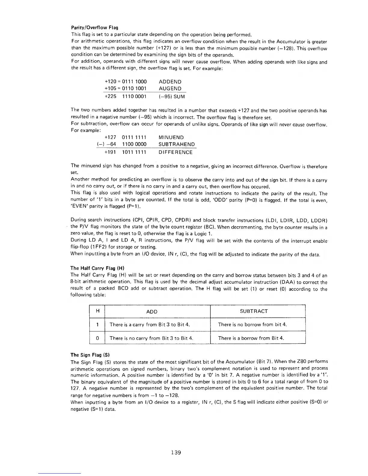
H
ADD
SUBTRACT
1
There
is
a carry
from
Bit
3
to
Bit
4.
There
is
no
borrow
from
bit
4.
0
There
is
no
carry
from
Bit
3
to
Bit
4. There
is
a
borrow
from
Bit
4.
The Sign Flag (S)
The Sign Flag (S) stores the state
of
the
most
significant
bit of
the
Accumulator
(Bit
7). When the
Z80
performs
arithmetic
operations on signed numbers,
binary
two's
complement
notation
is
used
to
represent and process
numeric
information.
A positive
number
is
identified
by a
'0'
in
bit
7.
A negative
number
is
identified
by
a
'1
'.
The
binary
equivalent
of
the magnitude
of
a positive
number
is
stored in bits 0
to
6
for
a
total
range
of
from
0
to
127. A negative
number
is
represented by the
two's
complement
of
the equivalent positive
number.
The
total
range
for
negative numbers
is
from
-1
to
-128.
When
inputting
a
byte
from
an
1/0 device
to
a register,
IN
r, (C), the S flag
will
indicate
either
positive
(S=O)
or
negative
(S=
1) data.
139

 Loading...