11-11
Interfacing with the MZ-800
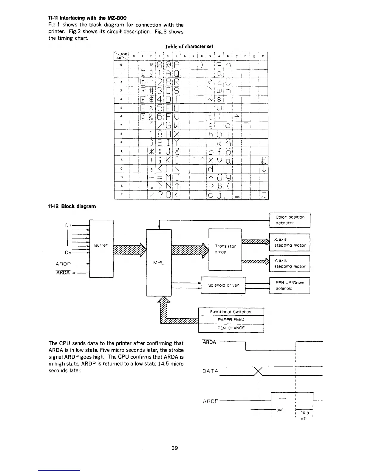
Fig.l shows the block diagram
for
connection with the
printer. Fig.2 shows its circuit description. Fig.3 shows
the timing chart.
Table
of
character set
11-12
Block diagram
Da---j
ARDP---1
ARDA
---;
Buffer
··,MSD
1
O
:
:
I
2
3
4
5
LSD--,
I
·-----
__,_
___
;_
I ' '
8;
!cl
p:
0 I ' : SP
i'
; :
--+---~----+-+-____j_\2::_
ol
I
Lw:2'1
A
-;-i
'[)!1':2'8
R:
I I
'I
' '
3
i
'Giir3iC
St
4
i
iBI$
4
D
Tl
I
I
I
i[8]1%
5
E
Ul
6
i
il9i8x
6iF
u
I
1/
7
1
G
w
7
I
I
8
iC
B:H
XI
9
i
i
'
j
91
I
y
I .
0
IJ
2'
A
I
·*~
0
I+
I
0
K
[
8
5
c
i
I 5
I<
L
""
I
D
I
i-I=IMI
]I
' I '
I
I 0
I)
N
t
E
i
l
I
l/
?
or~
F
I
MPU
The
CPU
sends
data to the printer
after
confirming that
ARDA
is
in
low state. Five micro seconds later, the strobe
signal ARDP goes high. The
CPU
confirms that ARDA is
in
high state, ARDP
is
returned to a low state 14.5 micro
seconds later.
39
6
i
I
i
i
I
I
!
i
'
.,
I
i
I
I
:
I
:
'
I
;
7
8
9
A
8
c
D
.._,
_____________
>
q
n·
I
I
i
I
__.____._._
!
:c
I
il
I
--
.,
I
I
··e.z:u:
I
--+-
i
"
'w:m:
I
!
! ; I
!
:"":s
i
i
I
I
iui
i
i
I I
I
l t:
I
I
-7
~
I
I i
' I
I
I 9
~
0!
i
=>'
! I
i
1hib
1
! i
!
I
i
I
I
I
ik
A'
!
I
! I
I
I
lb'i
floi
I
i
I
I
--=-!--
0
iAIXiV~(j!
I
I
i
l
I
I
I
!
i
idi
'I
I
i
i
i~:ljiyi
i P!
,8
i {
i
I
I
I !
!c:J
=I
Transistor
array
Solenoid
driver
l
i
i
!
i
Functional
Switches
PAPER FEED
PEN
CHANGE
ARDA
---...,
E
F
.I
I
I
I
!
I
I
i
if
1-t
I
!
i[
Calor
POSition
detector
X.
axis
steppino
motor
Y.
axis
stepping
motor
PEN
UP/Down
Solenoid
DATA
________
~><~-------~------
ARDP---------~~
14.5
pS
L
I
I

 Loading...