4-7
Register functions
VRAM
configuration
• One
or
two
chips
of
16
KB
VRAM are used.
• In
the
case
of
a
single
16
KB
VRAM chip, it
handles
320 x 200 dots, 4 colors,
or
640 x 200
dots
1 calor.
• In
the
case
of
two
16
KB
VRAM chips,
it
handles 320
x 200 dots, 16 colors, 640 x 200 dots, 4 colors, 320 x
200 dots, 4 colors, 2 frames,
or
640 x 200 dots, 1
calor,
two
frames.
* Discussed
next
are
about
functions
of
the
custom
LSI.
There
may
be
some
restrictions
because
the
standard
version
of
the
MZ-800
incorporates
only
one
16
KB
RAM.
Display
mode
register
(OUT
&HCE)
•
lt
consists
of
four
bits
which
are used
to
represent
display
method,
resolution,
and
display
screen
(calor
plane) in
combined
way.
Display
mode
register
(DMD)
MSB
DMD
2
DMD
1
LSB
DMD
0
•
DMD
3, 2: Display
method
and
resolution
DMD
2
3
0
0
Bit map, 320 x 200
0
1
Bit map, 640 x 200
1
0
MZ-700
mode
1
1
Prohibited
•
DMD
1,
0: Display screen
designation
DMD DMD
320 X 200
640
X 200
1 0
0 0
Frame A, Planes I and
II
Frame A, Plane I
0
1
Frame
B,
Planes
m
and
IV
Frame
B,
Plane
m
(NOTE)
1
0
Planes
I,
II,
m,
and N
Planes
I,
m
1 1
Prohibited
NOTE: 640 x 200, Plane B is Plane
m,
not
Plane
II.
•
With
the
MZ-800, DMD 1 =
0,
DMD 0 =
0.
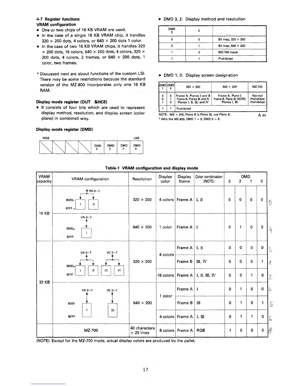
Table-1
VRAM
configuration
and
display
mode
VRAM
VRAM
configuration
Resolution
Display Display
Color
combination
DMD
capacity
col
or
frame
(NOTE)
3
2
c5?,_,
8000" G
320
X
200
4 colors Frame A
I.
IT
0
0
9FFF
H
16
KB
VA0-7
8000H
t
640
X
200
1 color
Frame A
I 0
1
8
BFFF
Frame A I, n 0
0
VA0-7
VC
0-7
~
4 colors
320
X
200
Frame B
m,
IV
0
I
0
-"~
I
II
9FFF
16
colors Frame A
1.
n.
m.
IV
0
0
32
KB
VA0-7
VC
0-7
Frame A I 0
1
i
l
1 calor
8000
0
G
640
X
200
Frame B
m
0
1
BFFF
4 colors Frame A
I. m
0
1
MZ-700
40
characters
8 colors Frame A
RGB
1 0
x
25
lines
(NOTE)
Except
for
the MZ-700 mode, actual display colors are produced by the pallet.
17
MZ-700
Normal
Prohibited
Prohibited
&.
3/3
1 0
0
0
0
0
0
0
0
1
1
0
0
0
0
1
1
0
0
0
0
4
'
'
~I
)

 Loading...