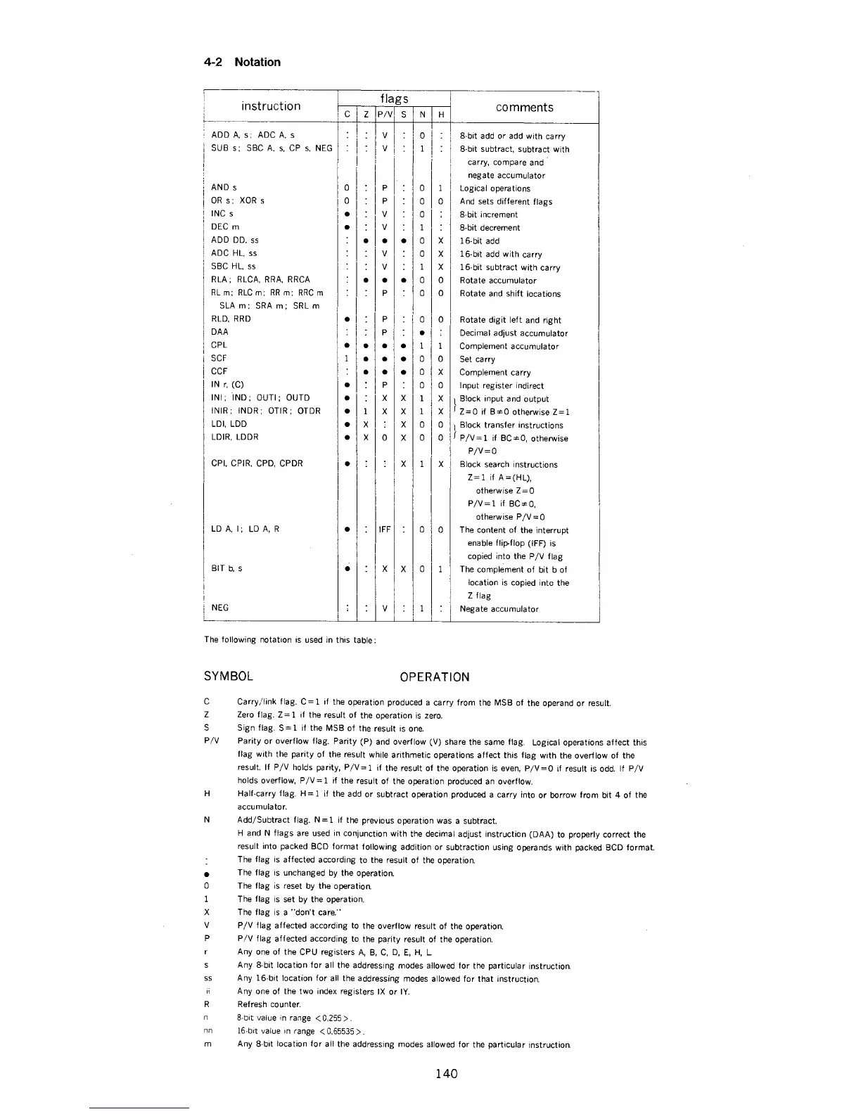
4-2 Notation
:
flags
'
instruction
comments
i
I
I
P/V
!
c
z
s
N H
I
ADDA,s;
ADC
A,
s
V
0
8-bit add
or
add with carry
SUB
s;
SBC
A,
s,
CP
s,
NEG
V
1
8-bit subtract, subtract with
carry, compare and
negate
accumulator
AND s
0
p
0 1 Logical operations
OR
s;
XOR
s
0
p
0 0
And
sets different flags
INC
s
•
V
0 8-bit increment
DEC
m
•
V
1 8-bit decrement
ADD
DD.
ss
• • •
0 X 16-bit add
ADC
HL,
ss
V
0
X 16-bit add with carry
SBC
HL,
ss
V 1
X 16-bit subtract with carry
RLA;
RLCA,
RRA,
RRCA
• • •
0 0 Rotate accumulator
RL
m;
RLC
m;
RR
m;
RRC
m
p
0 0
Rotate and
shift
locations
SLAm;
SRA
m;
SRL
m
RLD,
RRD
•
p
0 0
Rotate
digit
left and
right
DAA
p
•
Decimal adjust accumulator
CPL
•
• • •
1 1
Complement accumulator
SCF
1
• • •
0 0
Set
carry
CCF
• •
•
0 X
Complement carry
IN
r,
(C)
•
p
0 0 Input register indirect
1Nl;
IND;
OUTI;
OUTD
•
X X
1 X
\
Block input and output
INIR; INDR; OTIR;
OTDR
•
1 X X 1
X
I
Z=O
if
B"'O
otherwise
Z=1
LDI,
LOO
•
X
X
0 0
1 Block transfer instructions
LDIR, LDDR
•
X 0
X
0 0
I P
/V=
1 if
BC"'
0,
otherwise
P/V=O
CPI, CPIR,
CPD,
CPDR
•
X 1 X
Block search instructions
Z=1
if
A=(HL),
otherwise
Z=O
P
/V=
1 if
BC"'
0,
otherwise P
/V=
0
LD
A,
I;
LD
A,
R
•
IFF
0
0
The content of the interrupt
enable flip-flop (IFF) is
copied into the
P/V
flag
BIT
b,
s
•
X X 0
1
The
complement of bit b of
location
is
copied into the
Z flag
i
NEG
V 1
Negate
accumulator
The following notat1on
IS
used in this table:
SYMBOL
OPERATION
C
Carry/link
flag. C = 1 if the operation produced a carry from the MSB of the operand
or
result.
Z
Zero
flag. Z = 1 if the result of the operation
is
zero.
S Sign flag. S = 1 if the MSB
of
the result is
one.
P/V
Parity
or
overflow flag. Parity (P) and overflow (V) share the same
flag_
Logical operations
affect
this
flag with the parity of the result while arithmetic operations
affect
this flag with the overflow of the
result. If
P/V
holds parity,
P/V=
1 if the result of the operation is even,
P/V=O
if result is
odd.
If
P/V
holds overflow, P
/V=
1 if the result of the operation produced
an
overflow.
H Half-carry flag. H = 1 if the add
or
subtract operation produced a carry into
or
borrow from bit 4 of the
accumulator.
N Add/Subtract flag. N = 1 if the previous operation was a subtract.
H and N
flags
are used in conjunction with the decimal adjust instruction
(DAA)
to properly correct the
result into packed BCD
format
following addition
or
subtraction using operands with packed BCD format.
The
flag is affected according to the result of the operation.
• The flag IS unchanged
by
the operation.
0 The flag is reset by the operation.
The
flag
is
set by the operation_
X The
flag
is
a
"don't
care."
V P
/V
flag affected according to the overflow result of the operation.
P
P/V
flag affected according to the parity result of the operation.
Any one of the CPU registers
A,
B,
C,
D,
E,
H,
L
Any 8-bit
location
for
all the addressing modes allowed
for
the particular instruction.
ss
Any 16-bit location
for
all the addressing modes allowed
for
that
instruction.
Any one of the two index registers
IX
or
IY.
R Refresh counter.
8-b1t
value
in
range <
0.255
>.
nn
l6-b1t value
>n
range <
0,65535
> _
m Any 8-blt location
for
all the addressing modes allowed
for
the particular instruction.
140

 Loading...