15
PG-C30XU
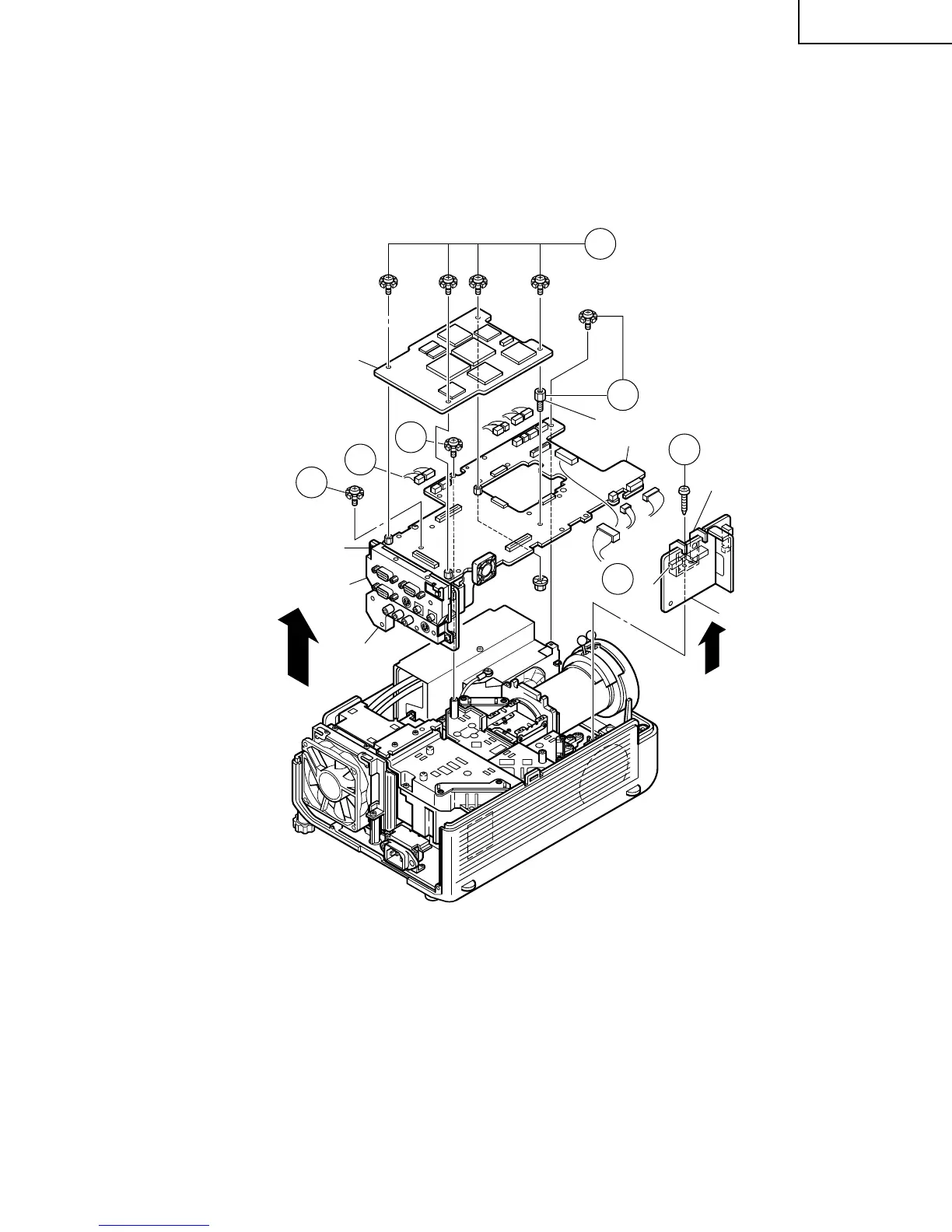
3. Removing the PWB units
3-1. Disconnect the connectors from the output unit.
3-2. Remove the four PC I/F unit lock screws, and take out the PC I/F unit.
3-3. Remove the spacer (stud bolt) and the three screws off the output unit. Lift the output unit, together with the
signal unit, off the position.
3-4. Remove the S-out/REG unit angle lock screw and take out the S-out/REG unit.
PC Terminal Unit
Video Unit
Signal Unit
PC I/F Unit
Spacer (stud bolt)
Output Unit
S-out/REG Unit Angle
S-out/REG Unit
3-1
3-1
3-2
3-3
3-3
3-3
3-4
(FP)
(FS)
(Q)
(FN)
(TP)
(EB)
(EB)
(SO)
(SP)
(EA)
(SO)
(F)
(L)