26
PG-C30XU
No. Adjusting point Adjusting conditions Adjusting procedure
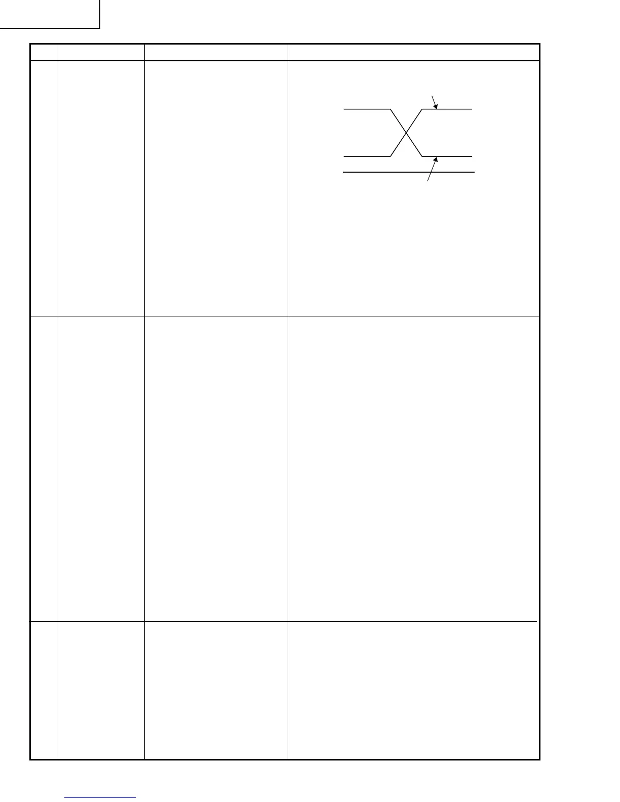
8 P SIGNAL 1. Connect the oscilloscope to
TP1701 for red.
TP1702 for green
TP1703 for blue.
2. Make the following choice:
Group : OUTPUT 2
Subject : PSIG-H
: PSIG-L
» Adjust the PSIG waveform to the one shown below.
9 Panel ghost
adjustment
1. Project the XGA60Hz ghost
test pattern (black charac-
ters in bold on the halftone
RGB background).
Group: OUTPUT3
2. GCK-PHASE adjustment
Make sure the setting is
fixed at 8 (initial value).
3. EN-WIDTH adjustment
Make sure the setting is
fixed at 8 (initial value).
4. ENR-PHASE adjustment
(R-LCD ghost adjustment)
5. ENG-PHASE adjustment
(G-LCD ghost adjustment)
6. ENB-PHASE adjustment
(B-LCD ghost adjustment)
» ENR-PHASE adjustment (R-LCD ghost adjust-
ment)
1 Increase the setting until a ghost image (see
Note) becomes visible at the left of the back
characters on the R half-tone background.
2 Lower the setting point by point until the left-
hand ghost image (1 above) disappears.
3 Further lower the setting by one point.
» ENG-PHASE adjustment (G-LCD ghost adjust-
ment)
Adjust the G ghost image by following the same
procedures described under step 1 above.
» ENB-PHASE adjustment (B-LCD ghost adjust-
ment)
Adjust the B ghost image by following the same
procedures described under step 1 above.
Note: Left-hand ghost image: Characters are shown
double 12 dots left from the real characters.
Reference: This adjustment is made because the
EPSON LCD panel may have 1- or 2-
point differences due to lot-by-lot
variations.
2.0V DC
7.3±0.2V DC
PSIG
GND
(Adjust with PSIG-H.)
(Adjust with PSIG-L.)
» For the green and blue colors, make sure their wave-
forms are similar to that of the red color.
» Make sure the pin stripe of every 12 dot doesn't ap-
pear at 10 steps signal of side nays.
(Appearing white pin stripe or black one, adjust the
PSIG-H.)
10 Sample-and-
hold pulse
phase
RCK-PHASE
GCK-PHASE
BCK-PHASE
1. Feed the XGA mode 75-Hz
black signal.
2. Make the following choice:
Group : OUTPUT 3
Subject : SH-PHASE
(Have the standard level at
2.)
Fix the RCK-, GCK- and
BCK-PHASE settings all to
8.
» Using the control switches or the remote controller
buttons, make sure that the “OUTPUT 3” charac-
ters are not blurry and there is no ghost image. If
such blur or ghost occurs, finely adjust the setting
in the range of 7~9.