5-2
The relevant terms.
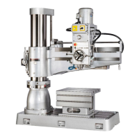
No. Term Description
1 Column It is to support the Gearbox and Arm. It is connected with the Base.
2 Top Cap It is on the top of the machine.
3 Electric ball screw It is the rail of the Arm, which can be lifted or lowered by an
elevating motor.
4 Main motor It is to move the spindle.
5 Three speeds change
lever
It is to change the speed of the Spindle. There are three speeds for it.
6 Two speeds change lever It is to change between the high and low speed. After interconnecting
with three speeds change lever, there are six speeds available on the
machine.
7 Hand wheel It is to move the head either to right or to left side.
8 Arm It is to support the Gearbox, connecting with the Column.
9 Lever, for feed trip. It is to start or stop the automatic Knives Feeding.
10 Hand wheel, for moving
head
It is the indicator for the automatic knife feeding. It runs
simultaneously with the feeding knives.
11 Spindle It is the place where drill bit, threading head, drill clamp are
mounted on.
12 Worktable It features a T shape chamfer, which help clamp and position work
piece. In addition, the worktable helps shorten the distance between
the work piece and the drill bit.
13 Base It is the gravity center of the machine. It stores the cutting fluids.
When no worktable used, it is used to support the work piece and
applied as a base for processing. It features also a T shape chamfer,
which is very convenient for clamping.
14 Cutting fluids adjusting
knob
It is used to control the floating of the cutting fluids.
15 Feed rate switch When at boring and automatic feeding needed, the feed rate varies
due to the different material and drilling bit used. It is used to adjust
the feed rate.
16 Handle, for rotating the
Arm.
It requires the smallest strength and it is the safest way to rotate the
Arm,
17 Control box All control elements are mounted here.
18 Counter weight After feeding knife finished, The spindle will return to its original
point due to the counter weight.
19 Metal covering It covers the internal ball screw and hydraulic pump so that the
operator or others can be safely protected.
20 Cutting fluids pump It is to pump the cutting fluids from the container to lubricate the
drilling or boring.
21 Elevating speed reducer The elevating motor rotates very fast. If the motor drives the ball
screw transmission directly, it is very hard to control the elevating
position. Therefore an elevating speed reducer is mounted to easily
control the elevating positions.
22 Elevating motor It is to elevate up or down the Arm through ball screw.
23 The solenoid valve It is to control the open and close of the switch when the Arm is
clamped hydraulically.
24 Hydraulic pump motor It is the source power for the hydraulic pump.
25 Oil tank It stores the hydraulic oil.
26 Oil pressure gauge
It indicated the oil pressure gauge. The normal pressure is 38bar。