EasyManua.ls Logo

Sharp RP-32 Series User Manual

Sharp RP-32 Series
12 pages
To Next Page IconTo Next Page
Page #1 background imageLoading...
Page #1 background image
mmm
SHARI=
S6458RP-32HS/
RP=32H(S)(BR)(BK)
RP=32E(S)
PHOTO:
RP-32H(S)
l
In the interests of user-safety the set should be restored to its
original condition and only parts identical to those specified be
used.
l
Im
lnteresse
der Benutzer-Sicherheit
sollte
dieses Gerat wieder auf
seinen
urspriinglichen Zustand eingestellt
und
nur die
vorge-
schriebenen Teile verwendet werden.
. Dans Iinterdt de la
sdcurite
de Iutilisateur, Iappareil devra
Btre
reconstitute dans
se
condition premiere et
seules
des
pieces
identiques
a
celles
specifiees,
doivent
Btre
utilisees.
INDEX TO CONTENTS
--.
0
Page
Page
SPECIFICATIONS . . . . . . . . . . . . . . . . . . . . . . .
.2,3
NOTES ON SCHEMATIC DIAGRAM
. . . . . . . . . .
.8,9
NAMESOFPARTS . . . . . . . . . . . . . . . . . . .
..a
.2,3
SCHEMATIC DIAGRAM AND WIRING
CARTIRDGE REPLACEMEMT . . . . . . . . . . . . . , . . 4
SIDE OF
P.W.BOARD
. . . . . . . . . . . . . . . . . . . . .
IO
PACKING METHOD (FOR UK) . . . . . . . . . . . . . . . . 5
EXPLODED VIEW . . . . . . . . . . . . . . . . . . . . . . . .
11
DlSASSEMBLY..........................6,7
REPLACEMENT PARTS LIST . . . . . . . . . . . . . . .
12
MECHANICAL ADJUSTMENT . . . . . . . . . . . . . .
6,7
@
INHALTSVERZEICHNIS
Seite
Seite
TECHNISCHE DATEN . . . . . . . . . . . . . . . . . . . .
.2,3
SCHEMATISCHER SCHALTPLAN UND
BEZEICHNUNG DER
TEILE
. . . . . . . . . . . . . . . .
.2,3
VERDRAHTUNGSSEITE DER LEITERPLATTE , .
10
AUSWECHSELN DES TONABNEHMERSYSTEMS . . . 4
EXPLOSIONSDARSTELLUNG . . . . . . . . . . . . . . .
11
ZERLEGEN
,...........................6,7
ERSATZTEILLISTE..
. . . . . . . . . . . . , . . . . . . . .
12
MECHANISMUSEINSTELLUNG . . . . . . . . . . . . .
6,7
ANMERKUNGEN ZUM SCHEMATISCHEN
SCHALTPLAN . . . . . . . . . . . . . . . . . . . . . . ...8.9
0
TABLE DES
MATIERES
Page
CARACTER~STIQUES . . . . . . . . , . . . . . . . .
.2,3
DIAGRAMME SCHf?MATIQUE ET COTE CABLAGE
Page
NOMENCLATURE. . . . . . . . . . . . . . . . . . . . . . .
.2,3
DE LAPLAQUETTE DE MONTAGE IMPRIME . . . IO
REMPLACEMENT DE LA CELLULE . . . . . . . . . . . . 4
VUE
E
N
&LATE
D~MONTAGE
11
6,7
RkiLAGE
DE
hi&Ikti;
:
:
:
:
:
:
:
:
:
:
:
:
:
:
:
:
6.7
LISTE DES
PIhE&%
kECHi&%
:
:
:
:
:
:
:
:
:
:
:
12
REMARQUES CONCERNANT LE
DIAGRAMME
SCHiMATlQUE
. . . . . . . . . . . . .
.8,9
/
SHARP
CORPORATION
Question and Answer IconNeed help?

Do you have a question about the Sharp RP-32 Series and is the answer not in the manual?

Sharp RP-32 Series Specifications

General IconGeneral
BrandSharp
ModelRP-32 Series
CategoryTurntable
LanguageEnglish

Summary

Specifications

Type and Technical Details

Details on the turntable's type, semiconductor components, speed, motor, and performance metrics like wow and flutter, S/N ratio, output, frequency response, and tracking force.

Tonearm and Cartridge Information

Specifications for the tonearm, including balance type, and details for the cartridge and replacement stylus.

Physical Dimensions and Weight

Information on the unit's overall dimensions and its weight.

Names of Parts

Turntable Components Identification

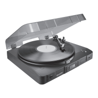
Identifies key parts of the turntable, including the record adaptor, spindle, turntable sheet, and the tonearm assembly.

Control and Connection Points

Details on parts like the cue lever, cartridge, cut button, speed selector button, and input/output plug.

Disassembly Instructions

Disassembly Precautions

Safety guidelines and important notes to follow before and during the disassembly process.

Mechanical Adjustments

Auto Return Adjustment

Procedure and points for adjusting the auto return mechanism of the turntable.

Phono Motor Speed Calibration

Instructions for adjusting and verifying the turntable's motor rotational speeds (33-1/3 and 45 RPM).

Packing Method for UK

Switch and Knob Settings for Packing

Specifies the correct positions for the cue lever and speed selector knob when packing the unit for the UK market.

Cartridge Replacement Procedure

Cartridge Installation Guide

Detailed steps for installing a new cartridge, including lead connections, headshell placement, and tracking force adjustment.

Notes on Schematic Diagram

Resistor Notation and Symbolism

Explanation of symbols used for resistors, including 'K' for 1000 Ohm and default Ohm notation.

Capacitor Notation and Symbolism

Explanation of symbols used for capacitors, including 'P' for micro-micro-farad and microfarad.

Diagram Update Disclaimer

Notice that schematic diagrams and wiring may be subject to change for product improvement.

Replacement Parts List

How to Order Replacement Parts

Information on how to order replacement parts, including required details like model number and part number.

Motor Schematic Diagram

Motor Unit Cautions

Advises against repairing the motor unit (RMōTV0184AFZZ) due to performance variations and recommends replacement.

Related product manuals