Service and Maintenance Manual 3-58 960714-02B © 2007 I2407
SECTION 3 – COMPONENT REPAIR
PHOTOELECTRIC SENSOR (con’t)
Use the following steps to replace the photoelectric
sensor.
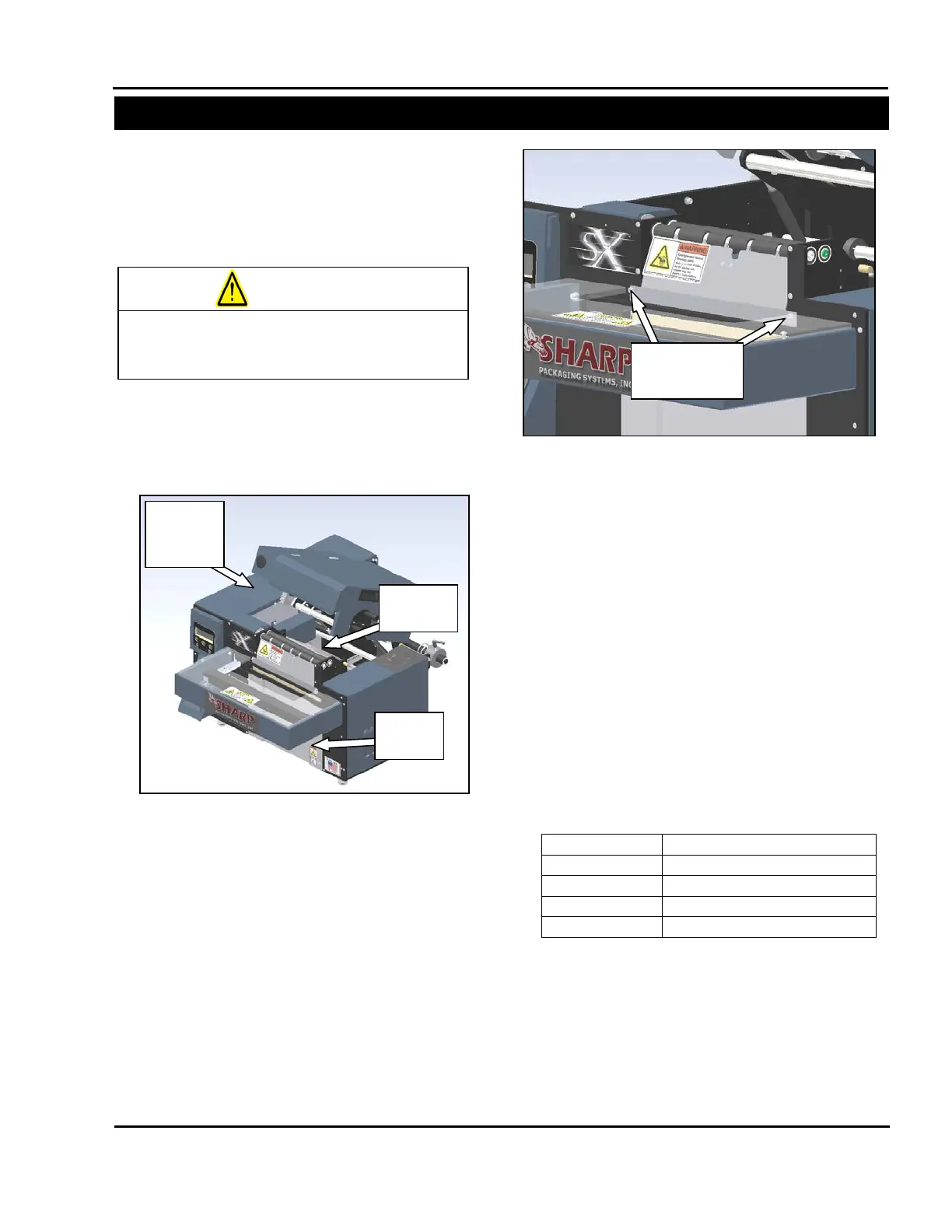
1. Remove the frame guard, the load plate, and
the motor cover (Figure 3-147).
2. Remove the two screws that hold the front
finger plate onto the machine (Figure 3-148).
Be careful not to pull this plate away from the
machine too briskly, as the sensor is affixed to
it.
3. Remove the photoelectric sensor from the front
finger plate. This is done by removing two
screws from the bottom of the sensor.
4. Follow the photoelectric sensor wires back
through the machine and remove any cable
ties attached to the sensor wire as necessary.
5. Once the cable has been followed to the
electrical area, remove the wire duct cover and
gently remove the sensor wire.
6. Disconnect the wires from the terminals.
Wiring is as follows:
Figure 3-148. Front Finger Plate
Plate Screws
Always remove electrical power from the
SX
prior to performing any maintenance
Table 3-4. Photoelectric Sensor Wiring
Figure 3-147. Guard Identification
Frame