INTRODUCTION : CONNECTION OVERVIEW
1. OVERVIEW OF CONNECTIONS
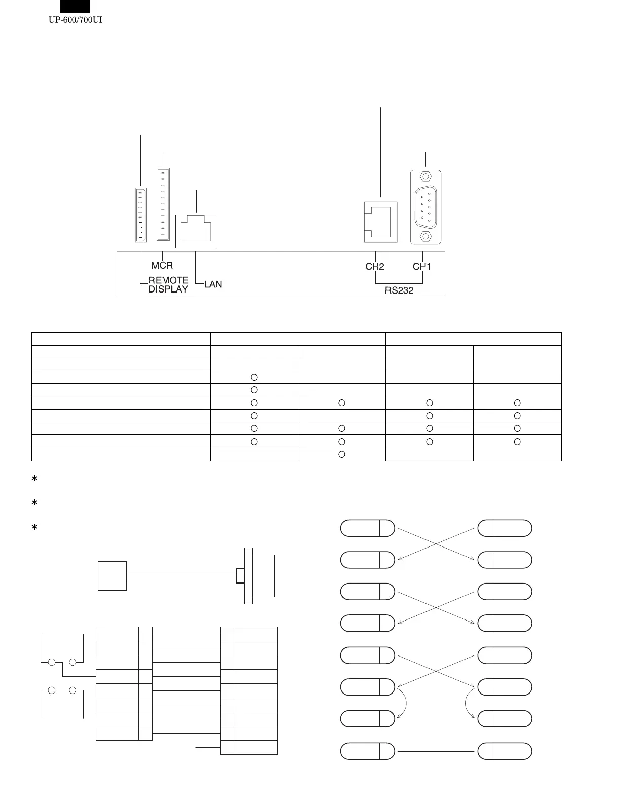
2. OPTIONAL DEVICES THAT CAN BE CONNECTED
Standard port Option port (ER-A5RS, ER-01EF)
Port No. Port1: CH1 Port2: CH2 Port3: Port4:
Type D-SUB 9pin Modular RJ45 D-SUB 9pin D-SUB 9pin
CI/+5V selectable
–––
ER-A6HS1 (+5V necessary)
–––
Scanner (+5V not necessary)
Modem –
PC
Printer, Scale
POS utility, ER02FD.exe – ––
The ER-A6HS1 cannot be connected to port 2, 3 or 4 because it
requires +5V.
The modem cannot be connected to port 2 because it uses a
different signal line.
For the RJ-45 modular to D-sub 9pin conversion cable, see the
following:
UP-P16DP
UP-E13MR
In-Line cable
RS232 devices
ER-A6HS1
and
RS232 devices
CD
CI
S404
7
4
3
1
5
2
6
8
9
/RS
/ER
SD
/CD
GND
RD
/RS
/CS
/CI
1
2
3
4
5
6
7
8
/RS
/ER
SD
GND
RD
/DR
/CS
(Open)
Moduler RJ45 D-sub 9pin
VCC
(+5V)
S403
GND
SD 3 SD
RD
CTS
RD
2
6
8
3
2
6
8
55SG
RTS
7
DCD
1
DTR
4
DSR
7
1
4
CTS
SG
RTS
DCD
DTR
DSR
9PIN DSUB 9PIN DSUB
D-SUB 9pin - D-SUB 9pin
cable
>>>>> USE FONT <<<<<
Helvetica/ Helvetica-Condensed/ Century-Schoolbook/ Symbol & OriginalFonts: (RingWorld2/RingFont2/Pa
Symbol/PartsCod)