UX-108U/178U/188U
FO-375U
[3] Circuit description of TEL/LIU PWB
(1) TEL/LIU block operational description
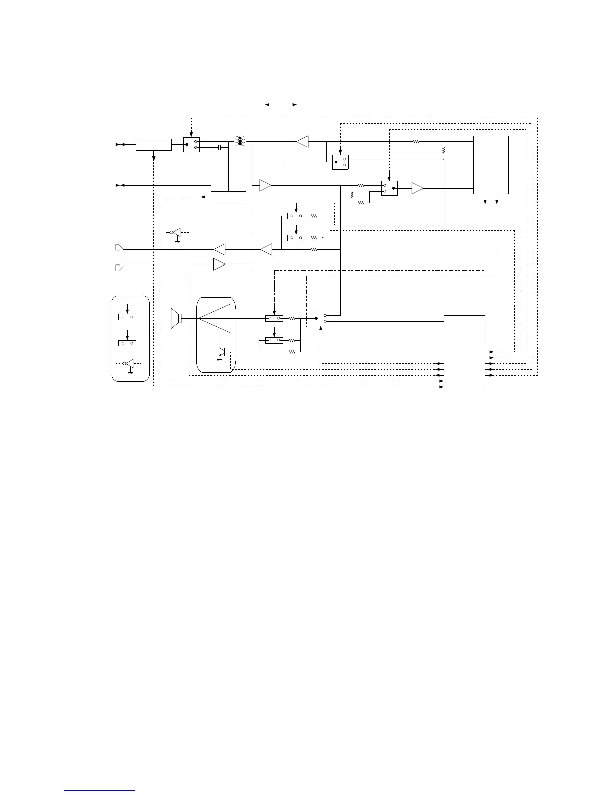
1) Block diagram
2) Circuit description
The TEL/LIU PWB is composed of the following 7 blocks.
1. Speech circuit section
2. Dial transmission section
3. Speaker amplifier section
4. Ringer circuit section
5. Externally connected TEL OFF HOOK detection circuit
6. CI detection circuit
7. Signal/DTMF transmission level & receiving level
Fig. 5
3) Block description
1. Speech circuit section
• The receiver volume is an electronic volume type, this model is
switch in 3 steps.
2. Dial transmission section
• D.P. transmission: The CML relay is turned on and off for control in
the DP calling system. (Refer to the attached sheet.)
• DTM transmission: It is formed in the modem, and is output.
3. Speaker amplifier section
• The volume of the ringer sound/speaker sound is controlled with
2-bit signal of VOLA and VOLB, and the sound switch is controlled
with BZ CONT.
4. Ringer circuit section
• The ringer sound is formed in the tone of 1-chip engine when CI
signal is detected. The amplifier circuit drives the speaker of the
main body.
CONTROL PWBTEL/LIU PWB
H
L
TX OUT
RX IN
1
0
0
1
HS DETECTOR
CI DETECTOR
SIGTX
SIGRX
CML GAIN-C
TX CONT
MODEM
(R96DFXL-CID)
VOL B
VOL A
RC VOL1
RC VOL2
TEL IN
TEL OUT
0
1
SP AMP
SP OUT
VOL B
VOL A
RC VOL2
BZ CONT
SP MUTE
TEL MUTE
CI
HS
BZOUT
RC VOL1
GAIN-C
TXCONT
CML
XFC3
H
L
HL
CML
TEL
LINE
EXT.
HANDSET
SPEAKER
5 – 8